Some Notable Examples of Unorthodox Construction
LOCOMOTIVES - 19

THE “CAMEL-BACK”, an appropriately-named locomotive used on American freight trains from 1848 to 1873. The driver’s cab was placed on top of the boiler to restrict the overall length of the engine, which had an exceptionally long firebox. Note the fireman's platform in front of the tender.
STEPHENSON’S “Rocket” of 1829 gave us substantially the steam locomotive as we have it to-day. Such further innovations as compounding, superheating, and high-pressure boilers are in the nature of refinements rather than radical alterations in practice. Only a few years after the “Rocket”, locomotive design had already begun to shed so many of the external peculiarities that distinguished the pioneer engines, that in the eighteen-nineties a well-known railway authority, referring to the Great Western’s “North Star”, built in 1838, said: “There is hardly anything in the external appearance of an engine built more than half a century since that would attract an ordinary non-technical eve if she were coupled up to a train at Paddington to-morrow.” But there have been plenty of unconventional locomotives since the very early days, and the supply is not yet exhausted. There have also been plenty of freaks, although the distinction between the freakish and the merely unconventional is often difficult to draw.
One reason for the appearance of so many unconventional locomotives in the early days was the disbelief entertained by so many engineers in the tractive power of the smooth wheel on the smooth rail. Hence such contrivances as locomotives designed to be worked by a species of propellers that were forced out backwards against the ground and then raised again, after the fashion of a horse’s legs. This device was patented both for locomotives and for “steam carriages”. Moreover, the pioneer builders seem to have had a curious aversion from the use of horizontal cylinders, as is to be seen in such typical examples as the “Rocket” and the “Invicta”. The latter was built by Robert Stephenson & Company for the Canterbury and Whitstable Railway in 1830, and was designed on much the same lines as the “Rocket”, save that its four wheels were coupled. This was, by the way, one of the earliest instances of coupling. Before the “Invicta” appeared the cylinders were often placed upright on the top of the boiler, whence motion was imparted to the driving wheels by a complicated structure of cranks and levers, the idea being derived, in principle, from Watt’s beam engine. An example of this design is Stephenson’s “Locomotion No. 1”, with which the Stockton and Darlington was opened in 1825. This also was a four-coupled machine, but the use of coupling rods was at the time still so unusual that “Locomotion No 1” almost qualifies for the epithet “unconventional” on this account alone. The earliest builders do not seem to have attached great faith to the coupling rod, preferring instead either spur gearing or chains, both of which were placed inside the frames.
While on the subject of these early engines we may recall the little-known fact that among the Stockton and Darlington’s original stud - it was, in fact, only the fifth to be built for the line - was a four-cylinder engine, which is generally believed to have been the first in which each pair of driving wheels was actuated by two pistons working on cranks at right angles to one another. But the machine was not a success; it “worked unsatisfactorily when on trial”, and “had been purchased for a small sum for the sake of its boiler and then laid aside.” The boiler was a little later used in the building of an historic locomotive, Hackworth’s “Royal George” of 1827. Hackworth claimed, although there is disagreement on the point, to have been the first to place the blast pipe orifice centrally with the chimney. Whoever was the originator, the builder of the “Royal George” was certainly no believer in the double exhaust, a detail of unconventional locomotive design that was at one time tried both in Germany and the United States, and also on the early Stockton and Darlington engines. The design has recently reappeared in France and on the LNER.
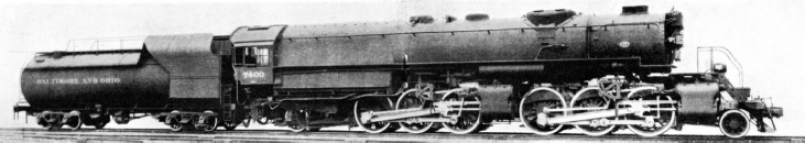
A SINGLE-EXPANSION ARTICULATED LOCOMOTIVE. This engine is of the KK1 Class, and was built by the Baldwin Locomotive Works in 1930 for freight services. The four cylinders are 23 in. diameter by 30 in. Stroke, and the outside diameter of the driving wheels is 5 ft. 10 in. The heating surface is large: the firebox area is 866 sq. ft., and that of the tubes 5,677 sq. ft., making a total of 6,543 sq. ft. The superheater area is 1,666 sq. ft., and the grate area 92 sq. ft. The tank capacity of the tender is 18,000 U.S. Gallons, and its fuel capacity is 20 tons.
Between the “Rocket” and the “North Star” we have to note the revival of a type of motion that had already been seen at an earlier day, namely the bell-crank transmission. As used in 1833 on the Dundee and Newtyle Railway, this embodied vertical cylinders mounted on the frames, the customary connecting rods, and double arm levers serving to link the connecting rods with the piston rods. This 1833 engine, the “Earl of Airlie”, had the unusual 0-2-4 wheel arrangement, which involved the placing of the cylinders and connecting rods behind the single driving wheels.
The “Earl of Airlie” is worthy of record, since in the following year the bell-crank motion was adopted for a number of locomotives for the Dublin and Kingstown Railway. In these locomotives, however, the single driving wheels were in the rear, and the cylinders in front of them. A general defect of the bell-crank was that it proved to be unsuitable for high speeds, owing to the pitching action resulting from the peculiar design.
Unconventional features were characteristic of practically all the designs of one of the great early British locomotive engineers, Thomas Russell Crampton. He was an ardent believer in a theory that carried a good deal of weight in its day, that of the low centre of gravity. He designed a six-wheeled locomotive, with large single driving wheels placed behind the firebox, and a relatively long boiler, pitched so low that the driving wheels overtopped it. Further details of Crampton locomotives, together with an illustration of one built in 1849 for the Northern Railway of France, will be found in the chapter “The Story of the Locomotive 2” in this work.
Indirect Drive
A variant of the Crampton locomotive was a “patent express engine” in which the drive was on to an intermediate crank-shaft, connected with the driving axle by a coupling rod. Engines of this type were built for the London, Chatham and Dover Railway and the Great Northern Railway.
TWENTY-EIGHT WHEELS. South Africa’s most powerful engine is of the Beyer-Garratt type illustrated. It was built in Manchester, and was specially designed to haul heavy goods traffic up the forty miles bank between Durban and Cato Ridge, on the Pietermaritzburg line. The wheel arrangement is
4-8-2+2-8-4.
Another and still more unusual arrangement of intermediate crankshaft was found on a locomotive built in 1848 for the South Yorkshire Railway. This was of the 0-4-2 type, with the crankshaft placed between the two driving axles, while the driving wheels, instead of being coupled, were each driven by separate connecting rods actuated by the crank. The design deserves the epithet of freakish, since there seems to have been no necessity for this complication of working parts. Since, however, the locomotive in question was at work for fourteen or fifteen years, it would seem to have adequately fulfilled the expectations of its builders.
The theory of the low centre of gravity found its extreme expression in the “Cornwall”, built in 1847 by Francis Trevithick, for the London and North Western. This locomotive had driving wheels of the exceptional diameter of 8 ft 6-in. As originally constructed, the “Cornwall” was a 4-2-2 with outside cylinders, and the boiler was placed below the driving axle. Among other peculiarities of design, the eccentrics were placed outside the driving wheels, and the regulator rod passed over the top of the boiler and entered the smoke-box below the chimney. The “Cornwall” was rebuilt in 1858 as a six-wheeler; the new boiler was placed in the normal position over the driving axle; even so, the driving wheels were flush with the top. This historic engine is still in existence; but it has so often been rebuilt that little of the original structure can be said to remain beyond the driving splashers and the name and number plates.
Large as were the driving wheels of the “Cornwall”, they did not establish a record. The 4-2-4 express tank engines of the broad-gauge Bristol and Exeter Railway, built in 1853-4, had 9 ft driving wheels; and the “Hurricane”, built for the Great Western Railway at Newcastle in 1838, had single driving wheels no less than 10 ft in diameter. Such a record is most unlikely to be beaten. The “Hurricane”, which was built under the patent of T. E. Harrison, who subsequently went to the North Eastern Railway, had another claim to distinction in that the boiler and motion were carried on two separate carriages. The same arrangement was adopted in the design of the “Thunderer”, built for the Great Western at the same time, and of identical dimensions, save that it had four coupled wheels 6 ft in diameter. These were not driven directly from the cylinder, but geared, the drive being by a “very broad wooden-toothed spur wheel, geared with a pinion wheel on to one of the coupled axles”. As the gear ratio was 27 to 10, this was virtually equivalent to the possession of driving wheels of nearly 17 ft in diameter.

BACK-TO-BACK. A Fairlie articulated engine used on the New Zealand Government Railways. Each locomotive is two engines in one, a single crew serving for both.
Details of the performance of these remarkable locomotives are scanty, but it is certain that the locomotives were not a success. The mounting of the motion on a carriage separate from the boiler (again the result of the low centre of gravity theory) resulted in insufficient adhesion, while the heating surface (623 sq ft) was not nearly enough for the 16-in by 20-in cylinders.
Among unconventional locomotives worthy of mention are the earlier Webb compounds. The special feature of these locomotives, which for many years hauled the fastest and heaviest passenger express trains on the London and North Western Railway, was that their designer dispensed with the use of coupling rods.
In 1882 appeared the “Experiment”. This had two independent pairs of driving wheels of equal size, and a small pair of leading wheels, the arrangement being known as 2-2-2-0. Two high-pressure cylinders, placed outside the frames, drove the back pair of wheels, and one large low-pressure cylinder the front pair. Thus the engines were described as “double singles”. Webb held “Experiment” to be a success, and he built four classes of these locomotives in the next eight years. These were followed in 1891 by the “Greater Britain” class, in which the introduction of a pair of trailing wheels made the wheel arrangement 2-2-2-2. These engines had very long boilers divided by a combustion chamber. “Greater Britain” herself visited the USA in 1893, and won a gold medal at the Chicago Exhibition of that year. After another and final series of “double singles”, Webb brought out in 1897 a four-cylinder four-coupled compound passenger express locomotive. In this engine the 4-4-0 wheel arrangement at last made its appearance on the London and North Western Railway.
In their day the Webb uncoupled compounds were the centre of a storm of criticism and controversy. One argument used against these engines was that the absence of coupling rods contributed to imperfect synchronization of the two pairs of driving wheels. Their coal consumption was also a subject of criticism, but it should be remembered that these compound locomotives hauled, without assistance, trains that bad previously been double-headed.

TURBINE DRIVEN, the Ljungström locomotive is capable of a speed of 85 mites an hour. The exhaust steam from the turbine is condensed and used again as feed water to the boiler..
THE TURBINE of the engine develops 2,000 hp at a shaft speed of 10,500 revolutions per minute. The high speed turbine shaft is geared to the driving wheels, and reversing is effected by introducing an idler pinion into the gear train. This locomotive made several trial runs in 1926 on the LMS Railway.
The next locomotive peculiarity calling for comment is the steam tender. To some extent Harrison may be said in the “Hurricane” and “Thunderer” to have anticipated the idea; but it found concrete expression in the locomotive introduced by Archibald Sturrock on the Great Northern Railway in 1863. The steam tender was not the invention of Sturrock, since a locomotive thus equipped was built for the Lyons and St. Etienne Railway by the French engineer Verpilleux as far back as 1843. In Great Britain, however, the design is particularly identified with the Great Northern Railway.
The salient feature of the Sturrock locomotives was that the tender constituted a separate engine, although fed from the boiler of the locomotive proper. The locomotives had six-coupled wheels, and the tenders also were six-coupled, the middle axle being cranked, and driven by two 12 by 17-in cylinders. Steam was taken from a second regulator in the dome through an external pipe to the tender, an arrangement that did not make for dryness, and the exhaust passed into a cond-enser on the tender, where it heated the water, and was finally exhausted through a chimney at the back of the tender. Over seventy of these engines were built for the Great Northern Railway, in addition to half a dozen for the Manchester, Sheffield and Lincolnshire Railway (subsequently the Great Central). They proved themselves capable of hauling heavy coal trains from Doncaster to London. But in practice the type had certain drawbacks. The engines were not economical in fuel, and, like the old “Hurricane”, the boilers were unequal to the task of steam generation. The steam tender locomotives were also unpopular with their drivers, who complained both of the excessive heat of the footplate and of having the equivalent of two locomotives to control. When Patrick Stirling, of “eight-foot single” fame, succeeded Sturrock, he converted the engines to normal pattern.
Early Articulated Locomotives
Another unconventional type is the articulated locomotive. Its origin is due to the search for an engine capable of negotiating sharp curves and yet powerful enough to pull an adequate load up severe gradients. The solution was found in the flexible locomotive. This is, in effect, two engines coupled together. In 1852 the Austrian Government offered a prize for the best design for a locomotive to work the heavy gradients of the Semmering incline. None of the designs submitted meeting with approval, an articulated locomotive was built for this line by the Belgian firm of John Cockerill. This had a double-ended boiler, with two adjacent fireboxes, carried on two bogies. The Fairlie locomotive, patented in 1864, differed from the Belgian engine in that a single firebox served both boilers. Later engines of this type, however, had separate fire-boxes. Fairlie locomotives were common enough abroad, but rare in Great Britain, where the curves are seldom sharp enough to demand special types. The earliest Fairlie locomotives in Great Britain were built for the narrow-gauge Festiniog Railway in North Wales.
The next important development was the Mallet articulated locomotive. This had a single boiler, but two sets of wheels and driving gear. Thus it was really two engines in one. Mallet’s locomotives were compound, the high-pressure cylinders driving one set of wheels and the low-pressure cylinders another. The design became popular in the USA. In 1924 the Baldwin Locomotive Works built for the Erie Railroad a triple-expansion Mallet locomotive driving three sets of eight-coupled wheels. The wheel arrangement is 2-8-0 + 0-8-0 + 0-8-2.
The Garratt locomotive, which is largely used in South Africa, among other countries, is a further development of the idea of articulation. This also comprises virtually two engines in one. In this design, however, the boiler has no wheels immediately below it, an arrangement that permits of a larger boiler diameter than would otherwise be possible; and the wheels, cylinders, and valve gear are placed beneath the tank at either end. A typical example is the 2-6-0 + 0-6-2 freight locomotive used on the London, Midland and Scottish for hauling heavy coal trains on the former Midland main line. Compounding is not employed. Each power unit has two outside cylinders, 18½-in by 26-in, and coupled wheels of 5 ft 3-in diameter; the weight in working order is 148 tons 15 cwt. These dimensions are exceeded by the Beyer-Garratt single-expansion locomotive built for the London and North Eastern Railway in 1925, which is of the 2-8-0 + 0-8-2 wheel arrangement. This has two three-cylinder units 18½-in by 26-in, weighs approximately 178 tons, and has a total heating surface, including superheater, of 3,640 sq ft. It is the most powerful locomotive in the British Isles.

HIGH PRESSURE streamlined locomotive No. 10000 on the turn-table at King’s Cross, London and North Eastern Railway.
In the Shay geared locomotive the problem of steep gradients and sharp curves is tackled in a different manner. In 1873 Ephraim Shay, operating an extensive sawmill in the Michigan lumber country, thought of a geared locomotive, in which the power developed by the engine might be transmitted through shafting to the wheels. An experimental locomotive proving successful, the idea was rapidly developed. To-day Shay locomotives of all sizes from ten to 160 tons are built. They are found useful in districts where the railway track has, for reasons of economy, to be laid on virtually unprepared ground. A powerful example of this type, weighing 160 tons, can haul a load of 200 tons up a gradient of 1 in 14, and develops a tractive effort of 74,400 pounds.
From the earliest days locomotive engineers have exercised their ingenuity in devising means of increasing adhesion, partly, although by no means entirely, in connexion with the problems of mountain railways. In fact, the rack-rail locomotive came before the opening of the Stockton and Darlington Railway; but the system was abandoned in England directly it was realized that the smooth rail on the smooth wheel provided sufficient adhesion. Then, in 1830, Vignolles and Ericsson patented a central friction rail, which demanded the use of locomotives fitted with horizontal friction rollers, set in operation by levers, and actuated by bevel wheels connected with the driving axles. No very extensive use was ever made of this system, but it is said to have been employed in Panama in 1847.
Mountain Climbers
In the eighteen-sixties came the Fell central rail system, in which an ordinary double-headed rail was laid horizontally between the running rails. The Fell locomotives had two sets of driving wheels, one of orthodox pattern, while the second, which was horizontal and actuated by separate cylinders, pressed against the horizontal rail. The necessary pressure was exerted through a system of levers and bevel wheels. Guide wheel for the central rail were also fitted at the trailing end.
The first Fell locomotives were built for the Mont Cenis Railway, after a test with an experimental engine on the acutely graded High Peak Railway, in Derbyshire. Locomotives of this type have also been used in Brazil.
Apart from the fairly common rack locomotive, a number of railways have made use of the combined rack and adhesion type, India and Chile being among the countries where they are to be found. A unique type, of which the first example was built in England in 1887 for the Puerto Cabello and Valencia Railway, South America, uses the rail wheels only as carrier, the motion being imparted by the Abt cog-wheels working on the rack rails. In the Kitson-Meyer locomotive the articulated principle is employed. In this the boiler, tank, and bunker are supported on two girders, which in turn rest on the bodies. Engines of this type were built in 1894, for the Nitrate Railways of Chile, whose line is characterized by a combination of heavy gradients and sharp curves. Fifteen years later Kitson-Meyer combined rack and adhesion locomotives were built for the Transandine Railway, which is on the metre gauge, and climbs to a height of 10,452 ft above sea-level.
The Transandine engines are unusual. In early examples the front unit was arranged for combined rack and adhesion work-ing, and had a small rack engine, while the rear unit was composed solely of a large rack engine. In later examples the supplementary rack engine was, however, abandoned, and the front unit was composed of only an adhesion engine, as it was found that this arrangement provided adequate power. The purpose of the auxiliary rack engine here was to provide a reserve of power to meet such contingencies as the formation of ice on the upper slopes of the line.
The auxiliary engine has also been used, in the form of the booster, both in England and the United States, as a source of reserve power on ordinary adhesion locomotives. The former Great Northern Railway fitted a booster to one of its “Atlantic” locomotives. A noteworthy modern example in British practice is the London and North Eastern “Mikado” (2-8-2), designed for handling heavy mineral traffic between Peterborough and London, capable of hauling a hundred laden coal wagons, and ranking next to the same company’s Garratts as the most powerful locomotive class in the British Isles.

“FIFTY-FIFTY”. A locomotive of the famous Garratt type used on the 2 ft 6-in gauge railway of Sierra Leone. The boiler, with cab attached, is slung between two similar power units, each carrying a water tank. The attachment of the boiler frame at either end to the power units allows the locomotive to negotiate very sharp curves.
These locomotives, which were the first in England to have the 2-8-2 wheel arrangement, have three cylinders 20-in in diameter by 26-in stroke; the coupled wheels have a diameter of 5 ft 2-in and the total tractive effort, when the booster is in operation, is 47,000 lb. The booster engine consists of a small power unit with two 10-in by 12-in cylinders, working on the trailing wheels, and with a tractive effort of 8,500 lb. Its object is to provide additional tractive effort when starting and on gradients. Action is semi-automatic; when the extra power is needed, the driver operates the booster latch, and the auxiliary mechanism then functions without further attention.
Many locomotive types merit the epithet unconventional not on account of any peculiarity in their mechanism, but as the result of unusual external design. In this category must be included a feature at one time not uncommon in the United States, in the shape of a cab perched centrally on the top of the boiler, an arrangement adopted in order to give the driver a better look-out. It has been used on the New York Central for passenger engines, and on the Lehigh Valley for goods engines. Locomotives of this type had two cabs, a second cab being situated in the orthodox position at the rear for the use of the fireman. The Southern Pacific Railway to-day uses oil burning tender locomotives having the cab at the front end and the chimney at the rear. The crew have thus an excellent look-out.
The “Decapod” tank engine was also of an unconventional design. It was built for the Great Eastern Railway in 1902 to show that the acceleration associated with electrical working could be obtained with steam. The “Decapod” was able to attain thirty miles an hour in thirty seconds from the dead start with a 300-ton train. Only one example was built. This locomotive had ten coupled wheels (0-10-0 arrangement), a working pressure of 200 lb, a laden weight of 80 tons, and a total heating surface of 3,052 sq ft. It was the first English tank engine to have three cylinders, and was also the first to have ten coupled wheels. For various reasons, including excessive weight, the “Decapod” saw little service. In 1906 it was rebuilt as an eight-coupled goods tender engine.
Our survey would be incomplete without a reference to the numerous types of locomotive designed for specialized conditions of service. Prominent among these are “fireless” locomotives, built for use on factory and dock railways, on lines serving mines and explosive works, and elsewhere when it is desired to minimize the risk of fire and explosion. The fireless locomotive is a steam engine requiring no fuel. It is charged with high pressure steam sufficient for several hours’ working, and the steam leaves the boiler and actuates the cylinders in the usual manner. These locomotives can be distinguished by the absence of a chimney.
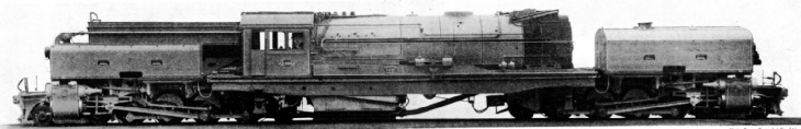
TRIPLE EXPANSION. This most unusual 4-8-0 locomotives, built for the Delaware and Hudson Railroad, has four cylinders - one high pressure of 20 in., one intermediate of 27½ in., and two low pressure of 33 in. diameter. They all have a stroke of 32 in. The tender is fitted with a booster. The driving wheels have a diameter of 5 ft. 3 in. The total area of the evaporating surface is 3,351 sq. ft, the superheating area is 1,076 sq. ft., and the grate area 75·8 sq. ft. The ten-wheeled tender takes 17½ tons of fuel and 14,000 gallons of water. The engine weighs, in working order, 171 tons, and the tender 122 tons.
Another specialized type is the crane locomotive, used for works purposes. This combines a locomotive with a crane, which forms an essential part of the design. A typical example, as used on the Great Western Railway, is an 0-6-4 tank, in which the crane is mounted at the rear, over the coal bunker, and, when not in use, is slung over and in line with the boiler. The crane itself can be swung through any desired arc.
It has already been mentioned that the line between the unusual or unconventional locomotive and the freak engine may be difficult to draw. Moreover the freak locomotive of to-day may merely be the forerunner of the most advanced practice of to-morrow. In such an indeterminate category must be included the turbine-driven and turbo-electric locomotives which originated in France and have been tested in England, but have not yet been developed to the stage at which they can be regarded as a commercial success. The LMS Railway has experimented with a 2,000 hp turbo-locomotive built in 1926 by Beyer, Peacock & Company to the designs of the Swedish engineer F. Ljungström. To the same class belongs the “uniflow” engine, which originated at least as early as 1845 - on the South Eastern Railway - where one was at work for over three years. The idea was revived in Germany by Stumpf about 1909. As used on the South Eastern, after the locomotive referred to had undergone alterations, the inside length of the cylinders was about twice the stroke, and the length of the piston nearly half that of the bore. In the middle of the cylinder was an exhaust port extending round half the circumference. When the piston stroke was nearly finished the steam was exhausted through the middle port into a pipe that passed out-side the cylinder barrel and entered the smoke-box from outside on the way to the blast pipe. The North Eastern Railway in later years built a 4-6-0 and a 4-4-2 locomotive with Stumpf “uniflow” cylinders.
The locomotive practice of the Great Western Railway was characterized by two features of special interest during the last years of the broad gauge - namely, tandem compounding and the construction of convertible engines. The latter were built as broad-gauge engines with a view to ultimate conversion to the narrow gauge, and were both four-coupled and “singles”. The “singles” underwent a double conversion. In their original form (when they had outside eccentrics) they were six-wheelers, and they remained so for a time after their adaptation to the narrow gauge. When they were converted to the
4-2-2 wheel arrangement they formed part of the company’s stock of eighty bogie “singles” that remained the standard for express passenger working for many years after the passing of the broad gauge in 1892.

STEPHENSON’S LONG-BOILER LOCOMOTIVE was patented in 1841. The three axles were placed under the boiler barrel, and the
5 ft 6-in driving wheels were flangeless to obviate lateral stresses on the crank axle. The engine weighed about 21 tons. The model shown in this picture was probably made in 1845.
Only two tandem compounds, originally constructed as 2-4-0’s and numbered 7 and 8, were built for the Great Western in 1886. Both had four cylinders, and were purely experimental. William Dean, who was locomotive engineer at that time, considered that, in view of the work that was being done by Webb on the North Western and Worsdell on the North Eastern, he ought also to try his hand at compounding. He utilized the tandem principle because of the special possibilities for experimental work in that direction.
No. 7 was built for the standard gauge, while No. 8 was a convertible locomotive. The former had high-pressure cylinders of 15-in diameter, as against 23-in for the low-pressure cylinders, and there was a common stroke of 21-in. By arranging the cylinders in line, a single piston rod could serve the high and low-pressure cylinder on either side. With No. 8, the cylinder diameters were 14-in and 22-in respectively, with a common stroke of 21-in ; and the low-pressure pair was placed in front. Neither was a success, the tandem principle having the disadvantage of involving heavy reciprocating masses.
Equally unsuccessful was the four-cylinder tandem compound built for the North British Railway in 1885, or rather reconstructed from a locomotive built in 1871 that was salved from the bottom of the river after the Tay Bridge disaster in 1879. This North British engine and the two Great Westerns were the only tandem compound ever built in the United Kingdom.
Of the two locomotives now to be described, only one of each pattern was built. These were the “James Toleman” and the Kitson-Still geared tank engine. The first was built in this country for the Chicago Exhibition of 1893, with the laudable aim of showing America what British designers could do in the way of speed. Its principal characteristic was an oval-shaped boiler.
A Geared Locomotive
Very little has been recorded of its performance, and the story that it insisted on running backwards during its Chicago trials is no doubt malicious; but it was certainly not a success, and, all things considered, may be regarded as coming within the category of genuine freaks.
Since a description of the Kitson-Still locomotive has already appeared in the chapter “Tank Engines”, beginning on page 481, it is only necessary here to mention its salient features. It was a four-cylinder simple 2-6-2; the cylinders were arranged tandem fashion to drive on a common crankshaft; the engine was geared at the ratio of 1.878 to 1; and the drive was not direct. The drive was taken on to gear wheels placed between the frames and carried above rail level, which transmitted motion to the first and second pairs of coupled wheels, This engine, which was built in 1927, attracted considerable attention at the time, but very little has since been heard of it. It may be pointed out, by the way, that the placing of the driving wheels above rail level was reminiscent of an arrangement that. has been used to a fairly large extent on rack and adhesion locomotives. A typical instance is the 0-10-0 type, built for the Netherlands East India State Railways for hauling mineral trains on a section having sharp curves. The coupled wheels are directly driven in the usual manner ; but there is also an auxiliary engine whose wheels are placed above track level, between the second and third coupled axles.
The ultra-high-pressure locomotive, which has been developed in Germany and Switzerland, has appeared in Great Britain both on the LMS and on the LNER. In the LMS “Fury”, a modified “Royal Scot” built in 1929, pressure reaches a maximum of 1,400-1,800 lb per sq in. The LNER No. 10000, of unconventional appearance and revolutionary design, appeared also in 1929. This engine had a water-tube boiler, with a pressure of 450 lb to the square inch. Neither of these types has been duplicated.
By way of conclusion, a most unusual locomotive may be mentioned. In 1872 there was opened a little line known as the Oxford and Aylesbury Tramroad, although it never reached within miles of either Oxford or Aylesbury. It was worked at first by horses, which were afterwards replaced by one of the most extraordinary locomotives ever seen in any country. The machine was a four-wheeler with a single large fly-wheel mounted on the boiler about five feet above rail level, and the whole affair resembled a steam roller that had provided itself with flanged rail wheels. The “steam roller” locomotive had a long narrow funnel crowned with a spark arrester, and a single cylinder placed above the boiler.

DRIVING EVERY AXLE, the Shay Geared Locomotive has twelve 4 ft wheels driven through gearing by three vertical cylinders, 17-in diameter by 18-in stroke. The weight of the engine, in working order, is 137½ tons. The tender has a fuel capacity of 9 tons, and can carry 6,000 gallons of water.
Read more on “Articulated Locomotives”, “Experimental Locomotives” and
“Giant American Locomotives” on this website.