© Railway Wonders of the World 2012-23  |  Contents  |  Site Map  |  Contact Us  | Cookie Policy

The Locomotive “Booster”

How the Tractive Effort of the Engine is Increased by Fitting an Independent Auxiliary Motor to the “Loafing” Trailer Axle


DESIGN AND INVENTION - 19


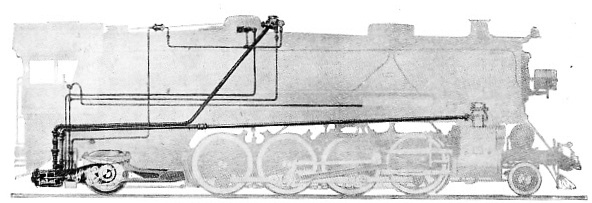
SCHEMATIC DIAGRAM OF BOOSTER AS APPLIED TO THE LOCOMOTIVE


SCHEMATIC DIAGRAM OF BOOSTER AS APPLIED TO THE LOCOMOTIVE. The trailing axle is converted into an independent motive-unit, and gives the extra power required at the critical moment in acceleration.


IN the struggle between steam and electricity for supremacy in railway operation one outstanding feature of the electrical principle is persistently driven home. This is the ability to squeeze out appreciably more power, When the occasion arises, to give rapid acceleration to the train. Without a doubt this represents an advantage over the familiar steam rival which cannot be ignored. It may be available for only a limited period, but, as a rule, this is more than sufficient to get the driver out of a tight corner. The “overload ” capacity of the electric locomotive constitutes a reserve of power which it is impossible to produce under steam conditions by conventional methods.


Obviously economy and efficiency demand that the load attached to the locomotive shall be the maximum the steam unit can haul at the required speed, and over the grades encountered, in accordance with the assigned timing schedule. We find this principle carried into effect in the composition of our trains, especially the long-distance high-speed expresses, where the weight of the train is the maximum limit coming within the hauling possibilities of the locomotive over the ruling grade, and which, if exceeded, even by a single coach, involves either the employment of a more powerful engine or recourse to double-heading to maintain the schedule.


The hauling capacity of the locomotive is governed by the relation between the tractive force developed and the resistance of the train. The more pronounced the difference between the two the greater the reserve for acceleration. As the speed increases, the tractive effort, or draw-bar-pull, diminishes, until, finally, the two balance, to maintain the constant or road speed so long as the track is level and other conditions are favourable.


The steam locomotive driver has always hankered for a means of getting a little more power out of his machine at critical moments to enable him to accelerate more rapidly to road speed. Many and varied devices have been evolved to satisfy this desire, but they have failed to substantiate their claims in practice. The draw-bar-pull is controlled by the weight which can be imposed upon the driving wheels of the locomotive, and the capacity of the boiler. In the great effort to derive the advantages from the range of road speeds, tractive effort has been increased by augmenting the number of driving wheels, and recourse to larger boilers, and this development is responsible for the extensive family of locomotives with which we are familiar.


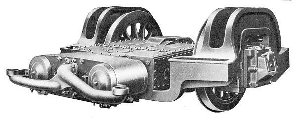
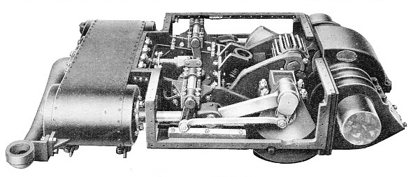
BOOSTER MOUNTED ON TRAILER TRUCK


BOOSTER MOUNTED ON TRAILER TRUCK. It comprises the fitting of a two-cylinder steam engine, or steam motor to the frame of the trailer. A single cast-steel bed-plate forms the bearings for the axle.


In this evolution other troubles have been precipitated, as, for instance, the necessity to introduce a truck, and pair of wheels behind the driving wheels, to support the fire-box and its weight, which have had to be increased proportionately with the boiler. In some instances, notably in France, four-wheel trailing trucks have been introduced, but whether the truck be two- or four-wheeled, it represents the addition of so much extra dead weight which has to be moved, thus losing a perceptible proportion of the advantage accruing from the imposition of increased weight upon the driving wheels. From the circumstance that the trailer wheels exercise no useful function in the tractive sense, they have colloquially become known as “loafing wheels”.


With the creation of larger and heavier locomotives the significance of the dead weight of the idle trailing axle became more and more apparent, and the attention of Mr. Ingersoll, the assistant to the president of the New York Central Railroad, became absorbed in the possibility of converting this adjunct to useful purpose. He conceived the idea of compelling it to perform dual duty.


His ultimate conception was novel. He converted the trailing axle into an independent motive-unit, to exert the same influence upon the steam locomotive as the overload capacity of the motor does upon the electric rival. In other words, he contrived an auxiliary, or reserve source of power, to assist the locomotive in starting, in tight places, and to accelerate it to road speed.


How the Booster Operates


To this invention he applied the generic name “booster”, and it was subjected to searching test on the bench, with the result that it revealed such promising possibilities as to induce experimental attachment in 1919 to a locomotive. Trials on the road fully substantiating the inventor’s expectations, the booster passed into established practice, and was introduced to the railways of the world through the Franklin Railway Supply Company, of New York City.


This device, one of the most ingenious recent improvements effected in the steam locomotive for the increase of power and enhancement of economical and efficient operation, has its functions fully explained by its title - it furnishes a boosting effort when desired. Its incorporation does not interfere with the design or normal operation of the locomotive, or the lay-out of the track, nor does it impose any additional duties upon the driver. When it is not furnishing power it is merely allowing the trailer to perform its carrying purpose; the difference is that this loafer can be made to work when required to give that little more power so often desired.

SIDE VIEW OF BOOSTER


SIDE VIEW OF BOOSTER. The simple engines have cylinders 10 inches in diameter by 12 inches stroke. They are of the double-acting type, and have their cranks set at 90 degrees.


It is a simple auxiliary comprising the fitting of a two-cylinder steam engine, or steam motor, to the frame of the trailer truck. A single cast-steel bed-plate forms the bearings for the axle, and also provides a third point of suspension for the truck. The simple engines have cylinders 10 inches in diameter by 12 inches stroke, are of the double-acting type, and have their cranks set at 90 degrees. The booster is fitted with a main transverse shaft on which is mounted a pinion, while on the trailer axle is another, and similar, but larger gearwheel. Between the two is a third gearwheel which can be thrown in and out of mesh to transmit the power from the booster shaft to the trailer axle; the gear ratio reads 14 to 36. The inter-mediate gear-wheel is moved from the cab by means of a bell-crank through a piston actuated by compressed air, and the admission of the steam to the booster engine is controlled by an auxiliary throttle.


The engine is of massive construction and completely enclosed, the gear cover forming an integral part of the casting. At the rear, or head of the cylinders, is a large manifold for the live and exhaust steam; the lead for the former is taken from the dome, while the latter is taken from the booster to the head of the locomotive to be exhausted with the steam from the engine cylinders through the blast pipe and smoke stack in the usual manner.


Control of the Booster


Control is semi-automatic. When the driver feels that his locomotive requires the extra power which the booster can give, he merely moves the controlling device mounted in his cab. The booster at once comes into action, and owing to the arrangement of its mechanism continues to operate without any further attention upon the part of the driver. It can even be set to cut out automatically when the locomotive has been accelerated to a certain speed; some of the power units thus equipped, and now running on the American roads, are so designed that the booster is arranged to drop out of action when a speed of 10 miles an hour has been attained.


Upon the American railways the “Mikado” design is generally accepted as the most efficient type of engine for heavy freight duty, though some systems have adopted the “Santa Fe”, or 2-10-2 type, for handling the traffic over their heaviest grades. By applying the booster to the “Mikado” type the tractive effort of the latter, for starting, is improved by 23 per cent. Translated into operation, as the experience of one system proves, the “Mikado” fitted with a booster can haul 392 tons more in the train than its sisters of identical design, but not fitted with this device. As a result, the increased earnings of the railway furnished with this unit exceed £5,500 during the year.


The train-load for a single locomotive is governed by the heaviest bank or ruling grade encountered in the course of the run. The bank may be short, and the train-load adapted to the limitations of the engine upon this incline may be far below the possible haul throughout the rest of the run. If it be desired to bring the load for the easier sections to the 100 per cent, hauling mark of the engine, this will be too much for the locomotive to move over the maximum rise. So for this section the services of a pusher locomotive must be retained to give the extra power to lift the load up the hill; the alternative is to divide the train. Experience has proved that with the booster sufficient additional tractive effort is forthcoming to dispense with the pusher.


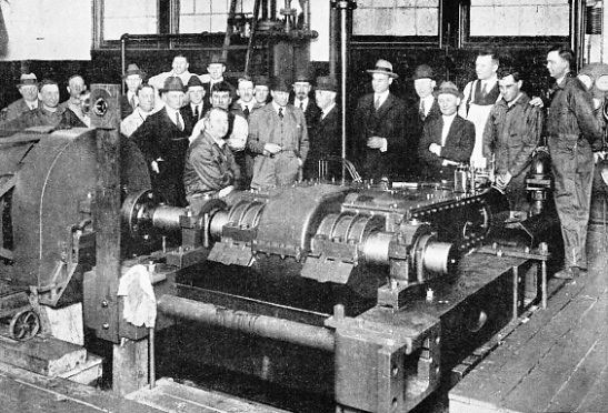
BOOSTER UNDER TEST ON BENCH-DYNAMOMETER


BOOSTER UNDER TEST ON BENCH-DYNAMOMETER

The device was subjected to searching test on the bench, and proved so satisfactory that in 1919 experimental attachment to a locomotive was carried out with equally good results.


As a rule, so far as it is practicable, the grades are grouped, or “bunched”, as it is termed, and the locomotive power selected for coping with the physical characteristics of that section. The succeeding division may be appreciably easier, rendering it uneconomical to continue the use of the locomotive employed upon the preceding section; one of less power will prove adequate for the purpose. It has been discovered, also, that the booster-equipped locomotive, normally handling the train over the easier division, can be employed for moving the traffic over the harder section by drawing upon the reserve energy offered by the auxiliary motor, so that two succeeding divisions can be rendered almost uniform, enabling the one locomotive to run through.


The extent to which this device is reducing pusher service is distinctly noticeable. On one road the pusher has been regularly employed to assist the train over 70 miles, though its services are not required continuously throughout this distance, nor its power demanded for more than 7½ miles. Now, a booster-equipped locomotive, identical with the road-engine previously employed, handles the train; the pusher engine is no longer required. In completing this 70 miles the aid of the booster is only required for a total of 23 minutes - to overcome the 7½ miles - which serves to reveal the wasteful employment of the pusher locomotive under previous conditions.


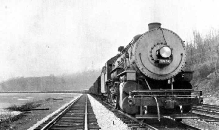
LONG FREIGHT TRAIN HAULED BY LOCOMOTIVE WITH BOOSTER


LONG FREIGHT TRAIN HAULED BY LOCOMOTIVE WITH BOOSTER. Above the piston valve cylinder is seen the header, or connexion, for the exhaust steam-pipe from booster to blast-pipe and smoke-stack.


In this instance the booster is saving the wages, fuel, and wear and tear of the locomotive which was employed as helper, as well as reducing the interference with the other traffic incidental to the pusher locomotive dropping back to its station. The booster represents an investment of about one-sixth of that of a locomotive, but it increases its tractive effort by approximately one-fifth. Consequently if five engines be thus equipped they are saving the acquisition of one locomotive, together with the wages and expenditure on fuel and maintenance.


In mountainous districts this economy becomes somewhat more pronounced. To a material degree the weight of the locomotives upon such sections is governed by the strength of the bridges and trestles. In this instance the booster fitted to the existing locomotive is able to solve the problem with eminent satisfaction, inasmuch as its inclusion only increases the weight of the locomotive by about 5,000 lb.
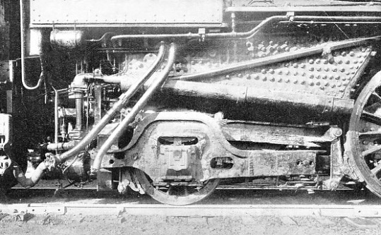

BOOSTER APPLIED TO LOCOMOTIVE


BOOSTER APPLIED TO LOCOMOTIVE. It is fitted with a main transverse shaft on which is mounted a pinion, while on the trailer is a similar but larger gear-wheel. Between the two, a third gear-wheel transmits the power from the booster shaft to the trailer axle, and is operated by a bell-crank through a piston actuated by compressed air.


This may be explained in another way. By fitting a locomotive of the 2-10-2 type, having a draw-bar-pull of 75,000 lb, and weighing 385,000 lb, with a booster, the weight factor is increased by only 5,300 lb, but the tractive effort is raised to 84,050 lb. On the other hand, a unit of the same type and class, developing 83,000 lb draw-bar-pull, without a booster, will weigh 420,000 lb. Here there is a net saving in the locomotive weight of approximately 30,000 lb, with an increase of more than 1,000 lb in tractive effort.


The booster also promises to revolutionize suburban train operation. In this service, especially during the hours of pressure, the train weights are heavy, while time is occupied in the acceleration to road speed upon leaving a station. It is this defect which has stimulated the electrification of the short-distance roads handling dense traffic. Experience is proving that the electric does not hold such a heavy advantage over the steam unit fitted with a booster. The latter gives just that extra turn of power for quick acceleration, thus enabling better timing and faster running to be made between the stations.


For the heavy suburban service of the American railways, extending up to 50 miles, powerful “Atlantics” were built, but they are proving inadequate for the traffic, and so are giving way to the “Pacific” type, which, however, yields far more remunerative performance on longer hauls. Certain railways have fitted boosters to their “Atlantics” and have discovered their starting effort to be improved 40 per cent, thereby, thus enabling them to release their “Pacifics” for the more remunerative duty. It may be mentioned, incidentally, that in the case of the “Pacific” type, the inclusion of the booster has been found to increase its starting effort by 27 per cent.


“PACIFIC” BOOSTER LOCOMOTIVE ON THE TEMISKAMING & NORTH ONTARIO RAILROAD


“PACIFIC” BOOSTER LOCOMOTIVE ON THE TEMISKAMING & NORTH ONTARIO RAILROAD. This line, traversing the hinterland of Northern Ontario and the Cobalt country, has heavy grades. By the inclusion of the booster, starting effort has been increased by 27 per cent.


The reserve of power which the booster represents ensures smoother and steadier starting, which, in the case of passenger trains, conduces to greater comfort in travel. Its advantages in this respect are brought home more effectively in connexion with the long freight trains, such as are common to the American, Canadian and other Dominion railways. Steady smooth starting reduces shock upon the draft-gear, especially in taking up the slack, which, in the case of a long train, may amount to 40 feet or more.


The trailer-booster, while representing one of the most notable advances in the efficiency of the steam locomotive during recent years, is merely the first step in a new channel of evolution. Since the conversion, at will, of the drone trailer wheels into workers the tender has received the attention of the inventor. This represents another heavy item in dead haul, amounting in the latest expressions of locomotive engineering to 100 tons or more. Experimenters are now applying the booster to this indispensable attribute of the locomotive; and some of the latest American locomotives are fitted therewith.

Investigation of the new development is proceeding in Great Britain, the pioneer effort in this direction being made upon the North Eastern division of the London and North Eastern Railway. The railway serves the busiest heavy industrial corner of the country, handling an enormous volume of coal, and having roads with somewhat severe grades; also, the marshalling yards have a dense traffic, and the operation of these can be appreciably facilitated with locomotives invested with the power to get away quickly.
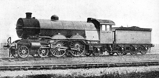

LNER EXPRESS PASSENGER ENGINE, “ATLANTIC” TYPE (4-4-2) FITTED WITH BOOSTER


LNER EXPRESS PASSENGER ENGINE, “ATLANTIC” TYPE (4-4-2) FITTED WITH BOOSTER. Built at Doncaster in 1906, this locomotive was rebuilt and fitted with booster in 1923.


You can read more on “The Development of the Locomotive Fire-Box”, “Firing the Locomotive Mechanically” and “Locomotive Accessories” on this website.