
© Railway Wonders of the World 2012-

Locomotive Accessories
Auxiliary Equipment of a Modern Engine
THE man who owns and drives a motor car knows that his car would be useless without certain important accessories. It is not generally realized that a steam locomotive similarly needs accessories. Every engine, for instance, must have a reliable means of feeding its boiler with water. An apparatus must exist to apply sand to the rails when they are too slippery to provide sufficient “bite” to start a heavy train. A whistle or hooter must be provided to give “audible warning of approach”; and so on.
Steam Injectors
One of the most interesting auxiliaries possessed by a locomotive is its injector, an instrument which apparently defies all the laws of nature by forcing water into the boiler by the direct action of its own steam pressure -
The injector was invented by a Frenchman, Henri Giffard, in 1859. Escaping the fate of many inventions, it was immediately adopted by many railway companies and locomotive building firms. The patent rights were taken up by Sharp, Stewart and Co. in 1860, and various inventors devised improvements, so that to-
The seeming paradox of an injector utilizing steam from a boiler to feed water into that boiler, thus overcoming its own pressure, may be simply explained. Let us suppose steam to be cold, so that a person might stand in a jet of it without being scalded. Now imagine two hose nozzles, from one of which steam at, say, 30 lb pressure is issuing, and from the other, a jet of water at the same pressure. Now, if anyone walked past these nozzles in the “line of fire”, he would pass the
steam jet with very little discomfort; but, on encountering the stream of water, he would probably be knocked over, or at least made to stagger. The steam, being unstable, and merely gas or vapour, can be resisted; not so the solid jet of water, which, though issuing from the nozzle at the same pressure as the steam, has a far greater power, by virtue of its being a “solid” body having a certain amount of momentum.
Carrying the illustration a step farther, let us imagine a jet of steam issuing from a nozzle attached to a boiler. Suppose we have a means of transferring to a jet of water the speed at which the steam issues from the nozzle. The water, having more “punch” behind it than the steam, as mentioned above, would force up the check valve and enter the boiler against the original steam pressure. The injector is the means by which this is carried out, and the operations are performed in the following manner.
The diagram shows the component parts of an injector in its simplest form, and this consists of a body, three cones, and a valve. The first cone is called the steam cone, and receives steam direct from the boiler via screw-

INJECTOR DIAGRAM. The above drawing illustrates the arrangement of the cones in
a steam injector. These may be arranged either horizontally or vertically, the principle
of operation remaining the same. Steam from the boiler enters the steam cone and
condenses in the water entering the injector through the inlet shown. The condensed
steam and water pass through the combining cone, enters the delivery cone and is forced
by its own velocity into the boiler. Excess water escapes through the overflow pipe.
The injector works as follows. When the steam is turned on, it issues from the cone at considerable velocity and enters the combining cone. As the nozzle of this is smaller than the steam nozzle, it cannot all get out, so lifts the valve and escapes there. Meanwhile the action has formed a partial vacuum in the space between the two cones, and water at once starts to rush in from the tank, as this space is connected to the water supply. Immediately the water enters the space, the steam strikes it and condenses in it, and a vacuum is formed in the combining cone, pulling the valve down tightly on its seat.
In condensing, the steam gives up its velocity to the water, and this is further accelerated by the vacuum in the combining cone, so that a stream of water flies from the nozzle of this cone at high speed. For a second or two after the action begins the jet will fluctuate a little in intensity, and some of it will go down the overflow pipe; but as soon as the jet is “fully established”, it shoots across the intervening space, enters the delivery cone, and proceeds up the delivery pipe, through the check valve, and so into the boiler. Should water continue to run from the overflow after the injector has begun to feed, too much water is being drawn in between the steam and combining cones. This can be regulated by a cock on the feed pipe, so that the overflow is “dry” all the time the injector is worked.
All injectors work on the above principle, but the types are many and varied. The original Giffard injector was similar to the above, except that the steam cone was made adjustable, and the water was regulated by sliding the steam cone in and out of the combining cone. Adjustable cones are not necessary in most types of modern injectors; and instead of the combining cone having a valve in it, a part of the wall of the cone itself is hinged, and lifts to allow surplus steam to escape when the injector starts. This type of cone is known as the flap nozzle. Another arrangement is to divide the combining cone into two parts, the front part sliding in the injector body. On starting, steam pushes the front part forward and escapes between the sections; but, on the injector beginning to feed, the vacuum in the cone draws the two parts together and presents an unbroken surface to the water.
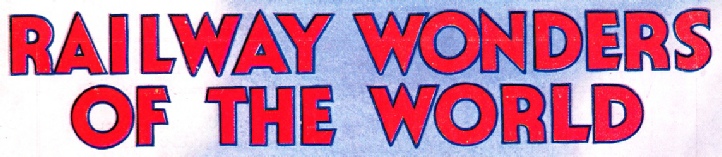
A MODERN INJECTOR is shown here, and the compact design of this important auxiliary to a locomotive is clearly indicated. Steam is taken to the top of the long casting at the right. On the left of the steam inlet is the cock controlling the water supply. Beneath the water cock is the flange to
which is bolted the overflow pipe. The flange at the bottom of the main casting, on the right, is bolted to a pipe delivering feed water to the boiler.
Present-
Exhaust Steam Injectors
Everybody who hears a locomotive “puff” must realize that the exhaust steam leaves the cylinders at considerable pressure. Engineers soon began to give attention to the problem of utilizing some of this pressure to work a special type of injector. The feat was accomplished, and the exhaust steam injector has now reached such a degree of perfection that a Davies and Metcalfe product has put water into a boiler, against 150 lb steam pressure, with exhaust steam at a pressure of 1 lb only. In principle, the exhaust injector is the same as the live steam injector, but the steam cones are duplicated; exhaust steam first enters the injector by a very large cone and “picks up” the water. A little live steam is then admitted by a supplementary cone, and gives the added impetus necessary to overcome the modern high boiler pressures. The feed water, after the two lots of steam have condensed in it, is usually at a temperature above that of boiling water at atmospheric pressure; and therefore some means of closing the overflow, after the injector has started working, has to
be fitted. If this were not done, the water would “flash” into steam as it passed the overflow chamber. A valve is fitted to the overflow outlet, and this is kept closed by a small piston connected with the delivery pipe, all the time the injector is working.
Donkey Pumps
Although the eccentric -
Briefly, the donkey pump consists of a steam cylinder and a pump cylinder arranged in line, the piston-
otherwise, as soon as the slide valve covered both ports of the steam cylinder, the pump would stop. The pump cylinder is double-
Feed Water Heaters
A common form of feed-

THE WORKING OF A FEED WATER HEATER
is illustrated by this drawing. Water from
Injector or feed pump enters through flange A,
passes clack valve B, and enters nozzle C, imparting a velocity that creates a slight vacuum around cone D. Steam is drawn in; this condenses and heats the water. Similar action takes place in cone E, which delivers the feed-
In some of the older locomotives, notably Beattie’s engines on the London and South Western Railway, and Stroudley’s on the London, Brighton and South Coast Railway, part of the exhaust steam was passed back into tender or tanks, and so heated up the whole body of feed water direct. This arrangement worked so long as no oil or grease went back with the exhaust steam, and eventually found its way to the boiler.
The ideal feed-

FEED WATER is heated by means of this apparatus, which is bolted in
duplicate to the top of a locomotive boiler shell. The flange on the left
is bolted to the water supply pipe from the injector or pump. On top of the fitting can be seen the adjusting screw which controls the lift of
the clack valve. The right-
immediately beneath this can be seen the openings to the two cones C and D indicated in the drawing above. The feed water is delivered to the boiler
through the out-
To obviate this trouble, a British firm, Messrs Gresham and Craven, Ltd, have introduced a top-
Soot Blowers
Passing from the water to the fire side of the boiler, it is imperative that as much of the heat as possible should be transmitted to the water. This is to be accomplished only by keeping the firebox sheets and the tubes clean and free from soot. The firebox is practically self-
The old-

CLEANING THE FLUES on a locomotive is accomplished by means of a steam soot-

DETAILS OF THE SOOT-
Soot-
On many engines, especially those of the former London and North Western Railway, on which the engines were often loaded to capacity, the heavy blast puts an excess of small cinders in the smoke-
Whistles
In the early days of the railways there were numerous level crossings -
But, after a train had demolished a farm cart containing a load of eggs and butter at a crossing, and the farmer had obtained compensation, a Leicester musical instrument maker was commissioned to make a “steam trumpet”, which was fitted to a locomotive, and proved a success.
Further details of this innovation are given in "The Story of the LMS”, which begins on page 925. From the “steam trumpet” was evolved the modern whistle, which, from a single note as used in Great Britain, has developed into the well-
Passengers on trains often hear a succession of long and short blasts, which cause children to wonder if the engine-
The Steam Blower
The long chimneys of the early engines provided sufficient natural draught to maintain the fire when the engine was standing; but, as boilers became bigger and chimneys shorter, it began to be difficult to maintain the fire and keep a full head of steam when waiting in a siding. One driver solved the problem by making a hole in the smoke-

A COMBINED PUMP AND HEATER for the boiler feed water fitted by Messrs J. Stone, Ltd, to a “Beyer-
From this simple device the steam blower was evolved. It is merely a ring of tube, in most instances, or possibly a casting resembling a domestic gas ring with a number of small holes in it, and is located on the blast pipe. Steam is turned into it by a cock or wheel valve in the cab, and the jets go up the chimney and so keep the draught working.
If the blower is not opened when the regulator is shut, and the engine is running, flames will often beat back through the firehole door; and several enginemen have been burnt through absent-
The Steam Sander
Though the “bite” of a smooth wheel on a steel rail is sufficient to haul a heavy load, the rails sometimes become wet and slippery, and the engine will slip badly unless sand is dropped. In early days there was no sanding gear, and firemen had to get down and shovel ballast under the wheels. Later, sand pipes were fitted, with funnel tops through which the fireman dropped sand from a receptacle on the engine. Later still, sand boxes, with pipes and valves, were fitted, so that sand could be dropped direct on the track rails; but this sometimes did not fall on the rails on a curve or in windy weather.

SANDING THE RAILS. This apparatus enables sand to be blown by means of a steam jet under the wheel of the locomotive, thus affording an adequate grip should the surface of the line be wet or grasy. Dry sand is carried in the box shown and falls by gravity to the bottom of the sand trap, where it piles up and so blocks its own outlet. When steam is turned on to the ejector a partial vacuum is created which draws in air from the opening shown to the left of the sand trap, so releasing the sand from the trap and forcing it under the wheel. On shutting off steam the sand again piles up in the trap, which is thus sealed until required again.
In 1886, Mr. Holt, Works Manager of the Midland Railway Works at Derby, designed an arrangement whereby sand could be blown under the wheels of a locomotive by compressed air; but, as this robbed the brake reservoirs of air, steam was substituted. The action of the steam and sand acts also as a cleaning agent on the rails. The bottom of the sand pipe has a small steam cone in it, resembling an ejector nozzle, which creates a partial vacuum in the sand pipe, drawing the sand over through a trap below the sand box, and then blows it directly under the wheels. The sand must be dry, so that it will flow freely. There is, however, another apparatus known as the Lambert wet sander, which uses water instead of steam, and delivers a kind of “sludge” under the wheels. With this type of sanding gear dried sand is not necessary.
Power Reversers
The weight of the motion on modern engines has become so great that it requires a substantial gear and a fair amount of physical strength on the part of the driver to operate the reverse. Power reversers, therefore, are often used, and are common in America, where big engines are the order of the day. The most common form embodies the principle of the “floating lever”. A cylinder is mounted at the side of the boiler and its piston is connected to the reverse or reach rod. This cylinder has a slide valve which is connected to the middle of a floating lever. The top of the lever is connected to a small handle in the driver’s cab; while the lower end is attached by a short rod to the crosshead of the reversing cylinder, or some convenient point on the reach rod.
Supposing the engine is in mid gear, the floating lever will be vertical, with the valve covering the ports on the reversing cylinder. On the driver pushing his lever to either end, the floating lever is tilted and steam is admitted to the reversing cylinder by the corresponding movement of the slide valve. But, as the other end of the floating lever is attached to the crosshead or reverse shaft, this end also moves in the opposite direction to the first movement, bringing the slide valve back to the original position, and cutting off steam from the cylinder after the desired movement has been accomplished. The floating levers are proportioned so that the slightest movement of the hand lever operates the valve and produces a corresponding movement of the power gear.
“Booster” Engines
We have already seen that it requires considerable power to move a train from a dead stand, but very little to keep it on the run once it is well away; and for most of a run a locomotive is working well under its maximum power output. It occurred to some engineers that if some means could be devised for temporarily increasing the power output, for starting purposes or for intermittent steep grade climbing, a much smaller engine could be used for a given load, with resulting operating economies. This led to the introduction of the “booster”, which is a small auxiliary engine driving one or more pairs of wheels on the engine or tender.
The idea is not new, for in 1863 one of the former Great Northern locomotive superintendents, Archibald Sturrock, designed some goods engines in which the tender wheels were coupled and driven by a pair of inside cylinders. They were not a success, because the boilers were not large enough to supply steam to what virtually amounted to two locomotives. They
differed from the modern booster-

LOCOMOTIVE CAB FITTINGS
The numbers are explained in the following key:
1. Train heating steam valve.
2. Auxiliary steam valve for exhaust injector.
3. Steam valve for live injector.
4. Vacuum brake gauge.
5. Boiler steam gauge.
6. Train heating steam gauge.
7. Water gauge (blow-
8. Water test cocks.
9. Main regulator with drifting valve attachment
10. Vacuum brake handle and valve.
11. Steam ejector handle.
12. Blower valve.
13. Hydrostatic cylinder lubricator.
14. Firehole door lever.
15. Axlebox lubricator.
16. Exhaust injector water cock handle.
17. Coal watering hose cock.
18. Damper handles.
19. Reversing screw and handle.
20. Front and back sanders.
21. Cylinder drain cock lever.
22. Live steam injector water valve handle.
23. Automatic train control apparatus.
X. Washout plugs.
The normal arrangement of the booster, as applied to the trailing wheels of an “Atlantic” or “Pacific” locomotive, or any other type having uncoupled wheels under the cab, is merely the provision of a small two-
The booster engine receives steam from the boiler direct or from the super-
When the booster is applied to a tender truck the action is just the same, but the wheels of the truck are sometimes coupled, as on the Sturrock steam tender, thus allowing the booster to exert more power than when driving a single axle.
Boiler Washing
In the chapter on “Driving a Locomotive” mention was made of boiler washing. In early days this was accomplished by connecting two hoses to hydrants in the engine shed alongside the pits, and squirting cold water at high pressure through holes in the smoke-
In some instances very large plugs of similar type were used to close the mudholes around the foundation ring, instead of the oval plate with “bridge” fastening. Modern boiler washing is done in a similar manner, but hot water is used, supplied either by a special hot main or by a portable boiler with injectors of a special type to suit the work.
Lubricators
The cylinders and valves of a locomotive need an unfailing supply of oil while running, and this is provided either by a mechanical or hydrostatic lubricator. The mechanical lubricator consists of a metal box, usually fixed on the running board, and containing four or more small pumps which are operated either by eccentrics or by a slide crank. Motion is given to the eccentric-
The hydrostatic lubricator has no working parts at all, oil being fed to the cylinders by the direct action of the steam. It consists of a box, on the front of which are four or more glass tubes. Each has a screwdown valve at the bottom, and a union at the top for connecting up the oil pipes leading to the cylinders and steam chests. Steam enters the oil box via a pipe and regulating valve connected to the boiler, and condenses. The water so formed raises the level of the oil and causes it to flow down pipes to the bottom of the sight-

FEED-
immediately behind the lamp on the buffer beam can be seen equipment which is often carried on locomotives overseas -
You can read more on “Development of the Fire-