Engines That Have Made Railway History
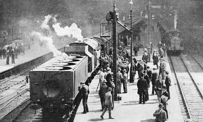
THE FIRST LJUNSTRÖM TURBINE LOCOMOTIVE, invented by a Swedish engineer, it was built in 1921, and achieved some success on the Swedish lines. A similar engine was built in 1924 in Britain, and this locomotive covered 5,402 miles during some months service on the LMS. Transmission from the turbine to driving axles was by triple gearing. At 75 miles and hour, the turbine made 10,500 revolutions a minute, and the maximum tractive effort was 40,320 lb. The locomotive is seen here at St Pancras Station.
FROM time to time efforts have been made by locomotive designers, both in Great Britain and in other countries, to break away from traditional locomotive design in search of greater efficiency - that is, to make better use of the energy develop-ed by the combustion of the fuel on the firegrate.
It cannot be disputed that, on the basis of thermal efficiency, the steam locomotive, in its ordinary form, is an inefficient heat engine. Taken over the whole course of its daily service, the overall thermal efficiency of the average steam loco-motive does not exceed, even in modern designs and test conditions, some seven per cent at most. That is to say, out of every hundred units of energy developed by the combustion of the fuel on the firegrate, ninety-three are wasted in various ways, and only the remaining seven are used in the haulage of the train behind the tender.
But this bald statement needs a great deal of qualification and explanation. In the first place, the steam locomotive suffers by reason of the confined space through which it has to pass. This self-contained power-station - as, in effect, it is - is limited in its cross-sectional dimensions to the dimensions of the loading gauge, so that it may pass through tunnels, under bridges, past platforms and other line-side structures, and so forth. Furthermore, it is limited in weight on anyone pair of wheels to the maximum that the track and the bridges can safely carry. And so, whereas the designer of the stationary power-station can layout his boilers and his machinery with little or no limitation in the way of space, and can erect a tall chimney to provide draught, the locomotive designer has no such freedom.
This matter of draught goes to the root of locomotive design. As it is impossible to erect a factory chimney on a locomotive boiler, some description of forced draught is essential, if there is to be proper combustion of the fuel on the firegrate. As far back as George Stephenson’s “Rocket” of 1829, we find the escaping steam from the cylinders, after it had done its work, led up into the chimney so that the suction thus created might provide a draught for the fire. And to this day the same principle persists.
Through the narrowed top of the blast-pipe in the smoke-box the expanded steam from the cylinders issues with such force that, as it passes upwards through the petticoat and out of the chimney, it creates a partial vacuum. To fill this, air is drawn through the ash pan and the dampers, providing the necessary oxygen for the complete combustion of the fuel on the firegrate, and the hot gases are then sucked through the boiler tubes to the smoke-box, so that every part of the boiler-heating surface thus takes a share in raising steam. In this connexion, also, it must be remembered - again because of the confined limits within which the design of the locomotive has to be developed - that the locomotive boiler is compelled to raise steam at a greater rate, in proportion to its size and weight, than any other type of boiler normally in use.
But even to the most casual observer it must be obvious, as the loudness of the engine “exhaust” is heard escaping from the chimney, especially on starting, and when travelling at low speeds uphill, that a great deal of power is thus being thrown to waste. The shortness of the boiler barrel also makes it inevitable that a considerable amount of heat from the fire is wastefully lost out of the chimney. Here, therefore, are direct and substantial losses of efficiency directly due to the principle
employed - the use of the partially-expanded steam from the cylinders to create the necessary forced draught.
It is for this reason that so much attention has been paid in recent years to valve-motions, to permit the modern loco-motive to be worked at a lower percentage of cut-off than previously. If, say, the engine is able to do its work on 15 per cent cut-off, instead of 25 per cent cut-off, then steam is being admitted for only one-seventh of the piston-stroke, instead of for one-quarter, and the work of the locomotive is being performed with a lower steam consumption. For this purpose a relatively long valve-travel is necessary, or there will be excessive compression behind the piston at the end of the stroke, and hot big-ends will probably result. At the same time, higher working pressures are introduced, so that the smaller volume of steam used in the cylinders during each stroke may have a greater initial capacity for expansion.
Exhaust Steam
The result of this development in valve-motions and cut-off percentages has been to lower the “terminal pressure” of the steam - that is, the final pressure at which it is released from the cylinders and thrown away up the chimney. This again must be obvious to the casual observer who remembers the continuous noise of locomotive exhaust in days gone by, and the showers of cinders on the carriage roofs, and compares these past experiences with the usual quietness of running at high speeds of the modern express locomotive. But even to these developments in efficiency there must be a limit. For the terminal pressure might get so low that ultimately it would fail to provide sufficient draught for the fire, and the boiler would refuse to steam.
There are many other factors which help to explain the low overall thermal efficiency of the steam locomotive. Though modern developments may succeed in raising the figure from seven to eight, nine, or possibly even ten per cent - which, in effect, would make the locomotive nearly half as efficient again as at present - it is unlikely, while the use of the steam to make draught still persists, that any higher figure can be reached.
Even if the working of the locomotive were absolutely perfect - that is, if the valve-motion permitted complete expansion of the steam right down to atmospheric pressure - the steam would still be exhausted as steam, and all the “latent” heat that has been used in effecting its conversion from water into steam would still be lost, so that a perfect locomotive of traditional design could not have a greater overall efficiency than fifteen per cent or so. Some consolation may be drawn from the fact that a modern power-station of the most advanced type, in which steam is the primary source of power, has no greater thermal efficiency than twenty to twenty-five per cent, even in the best conditions.
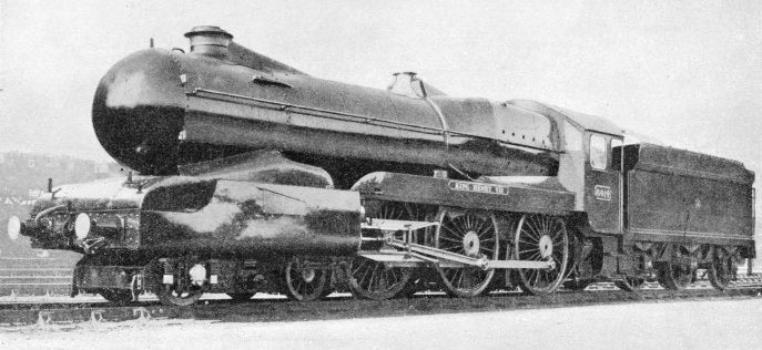
“KING HENRY VII”, one of the Great Western Railway’s famous “King” class locomotives, which has been partially streamlined in accordance with th latest developments in speed design. Similar streamlining has been applied to “Manorbier Castle” of the “Castle” class. After some experiencce of running, however, the cylinder casings have been removed from both engines.
It is not surprising that one of the first directions in which experimenters have turned to get over the difficulty of throwing steam to waste has been propulsion by turbines instead of by ordinary reciprocating motion. If turbine propulsion is combined with the use of a condenser, the exhaust steam with all its heat is trapped, instead of being thrown to waste. Not only so, but the partial vacuum resulting from condensation increases the efficiency of the turbine itself, so that there is a
double gain.
But here again, and to an even greater extent than in the design of a steam locomotive of the ordinary type, space and weight are crucial difficulties, especially in installing a condenser of the necessary size and capacity on a locomotive chassis. Other difficulties are that special forced draught (usually a fan) must be installed for the fire, independent turbines must be provided for reverse working, and gearing and other complications are essential, all of which influence initial cost considerably.
The first British turbine experiment was made in 1910, by the North British Locomotive Company, and the engine was designed jointly by the late Sir Hugh Reid and Mr. W. M. Ramsay. But the further complication of electrical propulsion was introduced, the turbine driving dynamos which produced the current used for the movement of the locomotive by means of
electric motors. The two ends of the frame were supported by eight-wheeled bogies. Propulsion was by four series-wound traction motors, of which the armatures were fitted to the driving axles, two on each bogie. One end of the frames carried a boiler of the locomotive type, and the other end the condenser. Superheated steam from the boiler was used in a turbine
of the impulse type running at 3,000 revolutions per minute, coupled to a continuous-current variable-voltage dynamo, which produced current at from 200 to 600 volts. Trials of the Reid-Ramsay turbo-electric locomotive were made on the Caledonian and North British Railways, but little information is available as to what happened.
Turbo-Condensing Engines
Next came a second turbo-condensing locomotive with electrical transmission, in the production of which Mr. Ramsay was again concerned. This was built by Armstrong, Whitworth & Company in 1921. Its design was similar in many respects to that of the engine just described. It was similarly carried on two groups of four axles, which in this example were coupled together; the driving wheels were 4 ft in diameter. The boiler was again at one end of the chassis and the condenser at the other. The main turbine was of the impulse pressure compounded multi-stage type, coupled to a three-phase generator which supplied current to four motors as before, with a total horse-power of 1,100. The total weight of the locomotive was 131 tons.
Later experiments dispensed with the electrical transmission. A handsome exhibit at the Wembley Exhibition of 1924 was the Reid-MacLeod geared steam turbine locomotive, built by the North British Locomotive Company. This was of a compound type, with a frame of exceptional length mounted on two eight-wheeled bogies as before. The turbines were mounted on the bogie frames, the low-pressure turbine driving the leading bogie, through reduction gearing, and the high-pressure turbine driving the trailing bogie. Normally, the engine was designed to run with the condenser leading and the chimney at the trailing end.
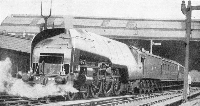
A WORKING PRESSURE OF 450 lb per square inch was planned in locomotive No. 10000 of the LNER by the use of a marine water-tube boiler, the first of its kind in Great Britain. The driving wheels are 6 ft 8 in in diameter, and the wheel arrangement is 4-6-2-2, as the firebox is carried on two fixed axles. The engine weighs 103½ tons in running trim. It has two inside high-pressure cylinders, 12 in by 26 in, and two outside low-pressure cylinders 20 in by 26 in.
Meanwhile some promising experiments had been made in Sweden by an engineer named Fredrik Ljungström, leading to the construction of a condensing turbo-locomotive of remarkable design in 1921. This consisted of two vehicles coupled together; the leading one carrying the boiler, and the second one the condenser, but the turbines, located between the two, drove the leading group of wheels under the condenser. The boiler vehicle had a bogie in front, and a group of three axles
carrying the firebox end; then came the group of three driving axles, driven by gearing, and another pair of wheels at the rear end which was used for reverse working. At 9,200 revolutions a minute the main turbine developed 1,800 horse-power. The whole locomotive was 72 ft long and weighed 126 tons. Some successful work was done by this locomotive on the Swedish railways, including the maintenance on the level of 60 miles an hour with a train of 475 tons; and it is also credited with having developed an overall thermal efficiency of 14·7 per cent. But no further engines of this type made their appearance in Sweden.
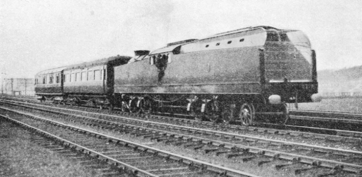
THE REID-MACLEOD GEARED STEAM TURBINE locomotive was shown at the Empire Exhibition, Wembley, in 1924. The engine was of the compound type mounted on tow eight-wheeled bogies. The turbines were placed on the bogie frames. The low-pressure turbine drove the leading bogie and the high-pressure turbine drove the trailing bogie. The illustration shows the engine on a trial run from Glasgow to Edinburgh.
This apparent success led the well-known British firm of Beyer, Peacock & Company to build a locomotive of similar type under the Ljungström patents. This was completed in 1926, and ran for some months over the Midland Division of the LMS, covering in all 5,402 miles. This curious-looking machine had a leading bogie, three pairs of wheels with outside frames under the firebox end of the boiler, a group of six-coupled driving wheels, of 5 ft 3 in diameter, under the leading end of the condenser chassis, and another bogie at the rear end, thus generally resembling in arrangement the Swedish engine.
Transmission from the turbines to the driving axles was by means of triple reduction gearing. At 75 miles an hour, the turbine made 10,500 revolutions per minute, and the maximum tractive effort developed at the drawbar was 18 tons. Steam was generated at a pressure of 300 lb per sq in. The complete locomotive weighed 143¾ tons in running trim. It proved quite capable of working ordinary express services on the Midland with heavier loads than those taken by the
compound 4-4-0 locomotives generally employed at the time, and made some very satisfactory runs But there was no reduction in coal consumption, and without the advantage of higher thermal efficiency the additional cost of construction
could not be justified.
In 1935 an entirely new British turbine experiment was made, in which neither electrical transmission nor condensing equipment was used. This was Engine No. 6202 of the London, Midland and Scottish Railway, which was built to the joint designs of Mr. W. A. Stanier, the Chief Mechanical Engineer of the LMS, and of the Metropolitan-Vickers Company, who supplied the turbine equipment.
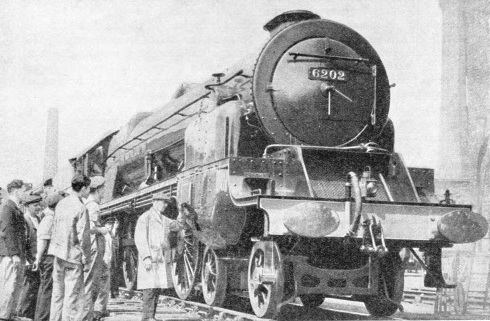 LMS “TURBOMOTIVE”, a turbine-driven engine introduced in 1935. The boiler has a total heating surface of 2,967 sq ft, the firegrate area is 45 sq ft, and - similar to other LMS “Pacific” type engines - the locomotive has 6 ft 6 in driving wheels. Engine and tender have a total weight in working order of 163 tons 13 cwt. The engine represents an interesting experiment in propulsion by geared turbine without condensing equipment.
The interest of this experiment centres not only in the trial of turbine propulsion without condensing, but also in the fact that it has been embodied in a locomotive which otherwise is of the standard LMS 4-6-2 type. A close comparison may thus be made, on a uniform basis, of the relative efficiency of drive with reciprocating motion, and of drive with geared turbines.
Steam is generated in the ordinary locomotive-type boiler, at 250 lb per sq in, and at a temperature of about 750 degrees Fahr, from which it is led to a steam casing formed as a steel casting. In this there are six hand-operated valves, operated independently at one another from the cab. From these nozzles the steam is led in flexible pipes to the high-pressure end of the turbine casing. which is at the left-hand side of the smoke-box. This houses the Lysholrn-Turbomotive type of turbine which provides for drive in the forward direction. The flexible pipes end in groups of nozzles; by opening the valves in succession, the drivel progressively applies more steam to the turbine, and the speed rises accordingly.
After use, the steam is exhausted in the ordinary way to the chimney, but a double blast-pipe and a double chimney provide for greater freedom of exhaust than in the ordinary smoke-box arrangement. Draught for the fire is thus provided for in the normal fashion, but a special design of blast-pipe compensates tor the fact that the pressure of the steam on exhaust is
lower than is customary with cylinder exhaust.
The turbine spindle, which is at right angles to the length of the engine, is coupled directly to the high-speed gear pinion, and the motion is transmitted to the driving axle by double helical reduction gear, enclosed in a gear-case of special design. As it is not possible to work the main turbine in reverse, a smaller turbine is installed on the right-hand side of the smoke-box for reverse running. This is of the impulse type, fed with steam by three control valves, and is brought into use by a mechanical clutch operated from the cab, with a safety device in the transmission to prevent the driver from attempting to reverse the locomotive except when it is motionless. Provision has also to be made for cooling the main turbine when the engine is running backwards.
A Successful Experiment
The boiler of the LMS “Turbomotive” has a total heating surface of 2,967 sq ft, to which the 32-elements superheater contributes 653 sq ft; the firegrate area is 45 sq ft. Uniformly with the other LMS “Pacifies”, the engine has 6 ft 6 in driving wheels. Engine and tender measure 74 ft 41 in over the buffers; the former weighs 109 tons in running trim, and the latter, with 4,000 gallons of water and 9 tons of coal, 54 tons 13 cwt, making a total of 163 tons 13 cwt.
The weight imposed upon the driving wheels. or the “adhesion weight”, as it is known, creates a new record for a six-
coupled British locomotive, as it totals 70¾ tons, two of the axles carrying 24 tons each. But this is permissible in view of the entire absence with turbine propulsion of the “hammer-blow” on the track which, in at least some degree, is present in all engines driven by reciprocating motion.
No. 6202 is now in regular working, and has hauled some of the fastest trains on the LMS main line, including the Liverpool express booked from Crewe to Willesden Junction at an average speed of 64.5 miles per hour, on which time was gained. As this run includes severe service slacks at Stafford and Rugby, a less severe slowing through Norton Bridge (Staffordshire), and another over the mining subsidence at Polesworth (Warwickshire), some very fast running is required.
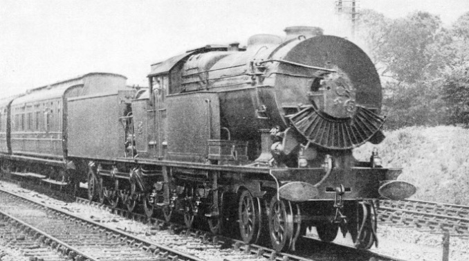
STEAM WAS GENERATED at the pressure of 300 lb per sq in in the 1926 turbine engine, tried out on the LMS. The locomotive successfully worked express services on the Midland Division of the railway. The engine weighed 143¾ tons in working order, and proved efficient in operation but though economies were effected they did not lead to the construction of other engines of this type.
Details have been received from the LMS Railway of two notable runs made by No. 6202 in working this train. On the first occasion, with a load of 331 tons tare (345 tons loaded), the 152.7 miles from Crewe to Willesden were run in 131 minutes, representing a gain of eleven minutes on schedule and an average speed of 69.8 mph. Two notable features were a minimum of 72 mph at the conclusion of the fifteen miles ascent from Bletchley to Tring, and a sustained maximum of 90 mph on the reverse slope of the Chilterns. On the second journey, with a load of 362 tons, the time from Crewe to Willesden was 138 minutes (overall average 66.2 mph), including an average of 75.6 mph over the 67.2 miles between Welton (Northants) and Wembley (Middlesex). The maximum speed on this second run, which was made under ordinary service conditions, was 86½ mph and the engine was not only running well within its capacity throughout, but was several times “eased” to avoid too early an arrival.
Up to the moment of writing no dynamometer car trials have yet been carried out with the “Turbomotive” such as would make available comparative data between its running costs and those of the standard LMS “Pacifies”. It is clear, however, that in performance alone - without any data being available as to possible fuel economies - the “Turbomotive” is capable of work indistinguishable from that of her standard sisters.
But the real success or otherwise of this revolutionary machine will be judged by whether or not its turbine propulsion increases thermal efficiency by reducing coal consumption. It is hoped that the lower exhaust pressure of the steam may have this effect, and that the cost of maintaining the turbine equipment will not exceed that of maintaining an ordinary locomotive; otherwise the increased constructional cost of a design of this description will have no justification.
Another line of locomotive experiment has been that of considerably higher working pressures, to increase the range of expansion through which the steam can be carried. Briefly, the purpose is that of increasing efficiency by making the same weight of steam do more work. But the difficulty is that a boiler of the ordinary type cannot successfully be designed to raise steam at a pressure higher than 275 to 300 lb per sq in.
High-Pressure Boilers
Novel types of boiler have thus been introduced to get over the difficulty. In Great Britain the best-known example has been the so-called “hush-hush” locomotive of the LNER, which earned its nickname in view of a certain amount of secrecy with which its construction in 1929 was surrounded. No. 10000, the engine in question, is the first in Great Britain in which a marine water-tube boiler has replaced the ordinary locomotive type boiler.
The process of steam-raising is in this way completely reversed. As high up as the loading gauge will permit, No. 10000 carries a drum, 28 ft long and 3 ft diameter, extending for most of the length of the engine, and containing water; a pair of drums on either side of the engine, 11 ft long by 18 in diameter, parallel with the upper drum, is carried along either side of the firebox, with a second pair, 13 ft 6 in long by 19 in diameter closer together, ahead of the firebox.
The lower drums are connected with the upper drum by a large number of water-tubes, arranged vertically in the form of an arch, of which the upper drum forms the crown. Within the arch is the fire-grate, which thus has all the area of the 238 water-tubes, 119 on either side, exposed directly to the heat of the fire; and the hot gases are then carried along past the second set of 444 tubes, 222 on either side, connecting the forward lower drums with the upper drum, until they reach the
chimney. Thus steam is raised by applying heat to the outside of water-tubes, instead of the heat being carried through tubes surrounded by water, as in the ordinary locomotive-type boiler. The working pressure of the engine is 450 lb per sq in.
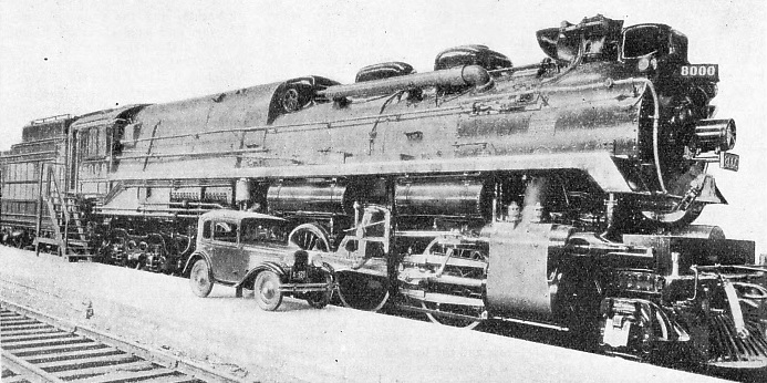
A GIANT SUPER-PRESSURE LOCOMOTIVE, No. 8000 of the Canadian Pacific Railway has two low-pressure cylinders, 24 in by 30 in, using superheated steam at 250 lb per sq in, and a high-pressure cylinder 15½ in by 28 in, using superheated steam at 850 lb per sq in. The tractive effort of this 2-10-4 engine is 90,000 lb, and the weight, including tender, is 392½ tons. The ten driving wheels are 5 ft 3 in in diameter.
To obtain adequate expansion, No. 10000 has been built as a compound locomotive, with two inside high-pressure cylinders 12 in diameter by 26 in stroke; and two outside low-pressure cylinders 20 in diameter by 26 in stroke. An ingenious arrangement patented by the designer of the engine, Mr. H. N. Gresley, allows variation of the cut-off in the high-pressure cylinders independently of that in the low-pressure cylinders, although only two sets of Walschaerts valve-motion are used. The driving wheels are of 6 ft 8 in diameter, and the wheel arrangement is 4-6-2-2, as the firebox is carried on two fixed axles, and not on a bogie. The engine weighs 103½ tons in running trim, and the tender, with the usual 5,000 gallons of water and 9 tons fuel capacity, weighs 62½ tons, making a total of 166 tons.
No. 10000 has taken its turn with the ordinary LNER “Pacifics”, including the working in the summer of such trains as the non-stop “Flying Scotsman” over the 392¾ miles between King’s Cross and Edinburgh. It is an open secret, however, that various unforeseen difficulties, arising chiefly out of the high steam pressure employed, have manifested themselves. Nevertheless much valuable information has been obtained from this bold experiment. Because of the height of the upper water drum there was no room available for boiler mountings, which had to be disposed of in various ways; the chimney was recessed behind large wings at the front end, which were provided to carry the exhaust clear of the cab windows. These, with the sheeting over the water-tube boiler, produced the first streamlined locomotive in Great Britain. A similar method has been adopted in the subsequent “Cock o' the North” and “Silver Jubilee” designs.
In the chapter entitled “Giant American Locomotives”, a description is given of the experiments which have been carried out by the Delaware and Hudson Railroad with high-pressure locomotives. By successive stages these experiments have produced locomotives with working pressures up to 500 lb per sq in, in boilers of special design. But this is by no means the limit.
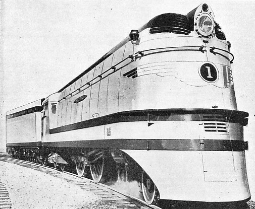
STREAMLINING IN AMERICA. The “Hiawatha” is one of the fastest trains in the USA; the photograph shows one of the locomotives of unusual design which haul the train. The “Hiawatha” covers the 280.8 miles between Chicago and La Crosse (Wis.) In four hours and eleven minutes, giving an average speed of 67.1 miles an hour, including three stops, and the entire 410 miles to St Paul in 6½ hours.
The German Schmidt-Henschel boiler is capable of raising steam at pressures up to 900 lb and even 1,000 lb per sq in. In this the sides, the front, the top, and the back of the firebox consist of a completely closed circuit of piping, communicating with longitudinal drums above and below and suitably cased in. This circuit is filled with distilled water, and in it the pressure may rise to anything between 1,400 and 1,800 lb per sq in; but the pressure of this water and steam takes no part in the propulsion of the engine.
Steam for propulsion is raised in the main high-pressure steam drum, which is not in contact with the fire, but contains tubular heating elements which form an integral part of the closed circuit, and the heat of which is communicated to the water in the drum through the tube walls. It is in this drum that steam is generated at 850 to 1,000 lb per sq in, and from here it is led to the high-pressure cylinder of the engine. After passing there through one stage of expansion, it is carried on to a receiver, in which it is mixed with steam generated in an ordinary locomotive type boiler, under the high-pressure steam drum, proceeding thence to the low-pressure cylinders, at a pressure of 250 lb per sq in or thereabouts, for final expansion.
An engine of this description, named “Fury”, was built by the LMS Company in 1929 on the same general lines as the “Royal Scots”, but after test was withdrawn from service. Similar engines have worked on the German State Railways, the Swiss Federal Railways, the PLM Railway of France, and the Canadian Pacific Railway, and have given good results from the thermal efficiency point of view. The Canadian Pacific locomotive, No. 8000, a 2-10-4 built for service in the Rocky Mountains, is claimed to be the largest super-pressure locomotive so far constructed.
In particular, the Swiss example, using steam at 850 lb per sq in, showed an economy of 35 to 40 per cent in coal consumption, and of 47 to 55 per cent in water consumption, as compared with an ordinary locomotive of generally similar dimensions. But the fact that none of these types has been multiplied beyond the original experimental stage suggests that the cost of maintenance and the constant need for repairs have more than outweighed the saving obtained from the higher
overall thermal efficiency.
Since the rapid increase in train speeds which has followed the introduction of high speed Diesel-propelled rail units, and has compelled locomotive designers, in defence of steam, to examine every factor bearing on high speed, the matter of scientific streamlining has come much to the fore. It is pertinent here to remark that a part at least of the success of high-speed Diesel units has been due to the fact that from the first the cars have been fully streamlined from end to end. Had the steam locomotives and trains with which comparison was first made been similarly streamlined, it is fairly certain that the differences in the maximum speeds which could be reached and maintained by Diesel and steam propulsion respectively would not have been so marked. But rapid progress is now being made in devising suitable streamlined coverings for locomotives designed to travel at high speeds continuously.
For probably it is only at speeds in excess of seventy or eighty miles an hour that streamlining begins to be really effective, so far as concerns a locomotive and train. Every projection from the surface of engine and coaches, and the space between engine and train, or coach and coach, are liable to cause eddy currents of air at speeds which cause the resistance of the air, opposing motion, to mount up. If that resistance can be reduced, then another source, this time external, of increased efficiency has been found. In France, as illustrated in the chapter “Through Southern France”, the Paris, Lyons and Mediterranean Railway provided its locomotives with “wind-cutter” smoke-boxes and cabs, with the object of attempting to secure some diminution of head resistance. But present-day streamlining is of a much more scientific description than that embodied in these early experiments.
In Great Britain it has found its fullest expression in the new “Pacific” locomotives designed by the LNER for the “Silver Jubilee” high-speed service between King’s Cross and Newcastle, which are fully dealt with in the chapter beginning on page 1436.
American Streamlining
An experiment of a more limited description was made in 1935 by the Great Western Railway, which provided two locomotives - “Manorbier Castle” and “King Henry VII” - with bullet-nosed smoke-box doors, wedge-shaped pieces tapering back from chimney and safety-valve casings, pointed fronts to the cab, and a sheathing over cylinders and motion. But it was found necessary to remove the sheathing, because of the tendency of the motion to heat when the cooling influence
of the outer air was thus shut off. In Germany two advanced designs of high-speed steam locomotive, fully streamlined, have been produced, One is a 4-6-4 express locomotive (illustrated on page 779 of this work) which is credited with having attained a maximum speed of 119 miles an hour when on test between Berlin and Hamburg. The other is a 4-6-4 tank for short-distance high-speed trains, similar in design but of smaller dimensions. In America, as described in the chapter
“Giant American Locomotives”, already cited, the most remarkable examples of complete streamlining are the “Commodore Vanderbilt” streamlined “Hudson” 4-6-4 type engine of the New York Central Lines, and the new “Hiawatha” 4-4-2 design of the Chicago, Milwaukee, St. Paul and Pacific Railroad, of which an illustration is given in this chapter.
The history of locomotive experimenting in modern times, therefore, seems in general to be that the advantages gained by radical alterations in the method of producing and utilizing the steam, though they may raise the overall thermal efficiency figure, tend to increase the costs of maintenance to such an extent as to force the locomotive engineers back to traditional
lines of design.
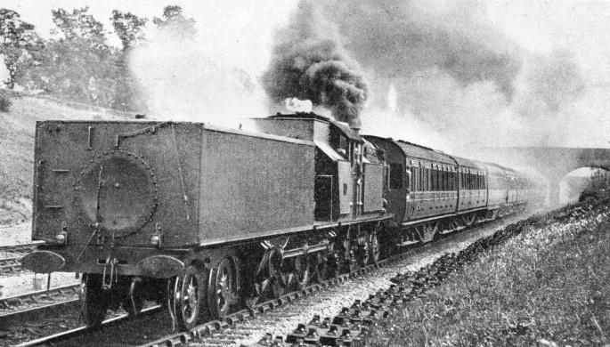
ON TRIAL. The Beyer Peacock Ljungström locomotive on the Midland main line near Mill Hill, Middlesex. The engine had a leading four-wheeled bogie, three pairs of wheels with outside frames under the firebox end of the boiler, six-coupled driving wheels of 5 ft 3 in diameter under the leading end of the condenser chassis, and a second four-wheeled bogie at the rear end.
You can read more on “A British Ljungstrom Turbine Locomotive”, “Giant American Locomotives” and “Speed Trains of North America” on this website.
You can read more on “Turbine Driven Locomotive” and “The Turbine Locomotive” in Wonders of World Engineering


 LMS “TURBOMOTIVE”, a turbine-


