© Railway Wonders of the World 2012-

How Mighty are the “Kings”
The Evolution and Working of the Great Western Railway’s Most Powerful Locomotive “King George V”
ONE hundred years ago the steam locomotive was the fastest means of transport, and only after the beginning of the present century did the coming of the motor-
Nearly a year before the opening of the world’s first commercially operated railway, between Stockton and Darlington, it was proposed that a line should link Bristol with London. A company was formed by a group of Bristol merchants to carry out the scheme. This proposal, although it did not materialize until some time later, was really the foundation of the Great Western Railway, the originators of the now famous “King” class of locomotive.
The first of these engines was the “King George V”, one of the most powerful express passenger locomotives in the British Isles.
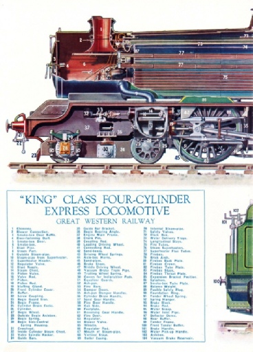
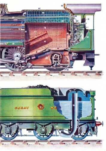
A modern express passenger locomotive such as the "King George V", presents to most people an appearance of bewildering complication. This impression can be dispelled at once, however, if the various components are considered separately. A coloured plate, showing a “King” class engine with part of the exterior cut away, is supplied with this number. If studied with the text it should render the working of the locomotive quite easy to understand.
The boiler, where power is generated and stored in the form of steam, will be dealt with first. The locomotive boiler comprises three units: the firebox where the coal is burnt, the barrel containing the bulk of the water, and the smoke-
At the bottom of the firebox is the grate, consisting of several cast-
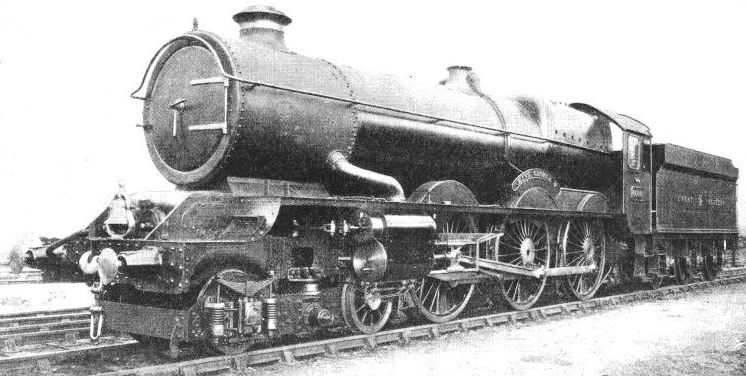
THE “KING GEORGE V”. The Great Western Railway’s most powerful express passenger locomotive, designed by Mr C B Collett CBE, the company’s chief mechanical engineer. This engine, built at Swindon Works, is 68 ft 2 in long over the buffers, and weighs in working order, with the tender, 135 tons 14 cwt. The locomotive has four cylinders, two inside and two outside the frames, supplied with steam at a pressure of 250 lb per sq in. The bell seen on the front buffer beam was presented by the Baltimore and Ohio Railroad of America, after the engine’s visit to the Baltimore Centenary Celebrations in 1927.
LOCOMOTIVE EVOLUTION ON THE GREAT WESTERN RAILWAY
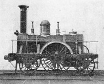
The “NORTH STAR”, was built in 1837. There were two cylinders 16 in diameter with a stroke of 16 in, supplied with steam at a pressure of only 50 lb per sq in. The driving wheels were 7 ft diameter.
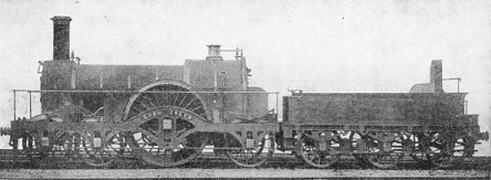
The “LORD OF THE ISLES” built in 1851, had two cylinders 18 in by 24 in, with 8 ft driving wheels and a boiler pressure of 140 lb per sq in.
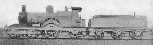
The “DUKE OF CONNAUGHT” is a fine example of the famous GWR “Single Wheelers”. Engines of this class, built in 1891-
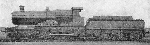
The “CITY OF TRURO”, a locomotive of the “City” class, was built in 1903, and the following year is stated to have attained the highest steam locomotive speed in railway history. The “Cities” were built with cylinders 18 in by 26 in, 6 ft 8½ in driving wheels, the boiler pressure being increased to 195 lb per sq in. This engine is now preserved in the Railway Museum at York.
The firebox is joined at the front end to the boiler barrel, through which pass a large number of tubes. These fire tubes convey the hot furnace gases through the water in the barrel to the smoke-
The firebox and the tubes give up their heat to the surrounding water, turning part of it to steam, which collects in the space at the top of the boiler. As more and more steam is generated its pressure rises until, at 250 lb per sq in, the spring-
Steam is taken from the boiler by internal pipes, upturned openings in which are situated just above the top of the front end of the firebox. This ensures that only dry steam is taken to the regulator or main steam valve in the smoke-
The boiler barrel is conical, the largest diameter being against the firebox, to take full advantage of the intense heat generated there.
A further advantage of tapering the boiler is the increased safety obtained, since the water cannot surge forward with the possibility of uncovering the top plates of the firebox. The danger of “running dry” a domestic boiler is, of course, well known, and no risks can be taken with such a huge steam generator as that of the “King George V”. As an added precaution, the firebox top, or “crown”, is fitted with a special plug of fusible alloy, so that in the remote possibility of the plates becoming uncovered, the safety plug melts and the steam rushes into the firebox, extinguishing the fire.
The regulator controlling the supply of steam to the cylinders is situated in the smoke-
Superheated Steam
From the regulator are taken long steel pipes, bent U-
The superheater pipes or elements are all led to a superheater “header”, or box, from which other pipes distribute the superheated steam to the circular “steam chests” which contain valves controlling the steam supplied to the four cylinders.
Each of these cylinders, closed by covers at the ends, contains a piston, as in a motor-
The coupling rods are jointed near the centre, because each wheel is free to move up and down within the limits of the controlling springs, and a rigid bar would snap as the wheels “give” to the inequalities of the track.
The steam chests are actually smaller cylinders situated above the power cylinders, and to these are led the steam pipes from the superheater. Passages lead from the steam chest to each end of the cylinder. Two piston-
These piston valves permit the live steam to enter first one end of the cylinder (the opposite end being open to the exhaust pipe in the smoke-

The “CAERPHILLY CASTLE” -

A “KING” CLASS LOCOMOTIVE with boiler in its “suit” of insulating material which prevents loss of heat by radiation. This coating is subsequently covered by thin steel sheets which are finally painted in the Company’s familiar green livery. In the foreground of this picture, taken at Swindon Works, can be seen the frame of another locomotive in course of erection, the cylinders having been already bolted in position, as shown to the right.
On the “Kings”, the Walschaerts gear, driven from the main driving axle and inside crossheads, operates the valves for the inside cylinders, the outside cylinder valves being worked from the inside gear by means of “rocking levers” pivoted on brackets secured to the engine frames.
It should be borne in mind that the piston is not subjected to the full boiler pressure of steam during the whole of its “stroke” through the cylinder. Steam is admitted for a part of the stroke only, but once in the cylinder it continues to expand, giving up its energy in moving the piston.
The direction in which the locomotive will run is governed by the position of the piston valves when the steam regulator is opened. The valve position is controlled by the driver’s reversing lever in the cab. This reversing lever has another very important function known as “notching-
The exhaust steam from the cylinders is taken to a “blast pipe” in the smokebox, which comprises a circular air-
The Giant’s Measure
The “King” locomotives have given astonishing service. They have not only proved capable of handling the heaviest traffic in accordance with schedule, but they have also been responsible for considerable economies in running costs -
The “King George V” is 68 ft 2 in long over the buffers, including tender. The size of the engine will more readily be appreciated when it is borne in mind that the driving wheels are 6 ft 6 in in diameter, over-
The “Kings” are referred to as 4-
The total weight of one of the “Kings” on the six driving wheels is 67½ tons, giving a load of 22½ tons on each of the three axles. The total weight of the engine in running order -
A unique feature in the design of the bogie is the method adopted to provide for the independent springing of the wheels. The axles of the leading wheel are carried in axle boxes placed outside the bogie frames, the trailing wheel axles having boxes inside the frames so that the rear end of the bogie may have room to swing between the cylinders when negotiating curves. There are four cylinders (each 16¼ in diameter with a stroke of 28 in), two of which are placed outside the main frames of the engine and drive the middle pair of coupled wheels. The other two cylinders are well forward between the frames, and drive the first, or leading, pair of coupled wheels. All six wheels are, of course, connected together by coupling rods, so that they turn in unison.
Four cylinders of such dimensions naturally require a steam generator of very large proportions, and the locomotive’s boiler, of typical GWR conical shape, is 27 ft 6 in long, with a firebox length of 11 ft 6 in, the grate area being just over 34 sq ft.
From the front end of the firebox hundreds of tubes pass through the boiler to the smoke-
The tender is of the six-

FITTING THE WHEELS of a “King” at Swindon. The partly completed chassis with boiler in place is lifted up by a powerful travelling crane, and is lowered on to the wheels on the track beneath. The outer boiler covering of steel plate has in this instance been attached, but the insulation on the firebox has still to receive its protective coating of steel.
The “Kings” have proved themselves fully capable of hauling the fastest and heaviest expresses of the Great Western Railway. The first service run, in fact, of the “King George V” was accomplished in under scheduled time with the Cornish Riviera Express from Paddington to Plymouth -
Power and Performance
The famous Dainton and Rattery banks, ranging in steepness from 1 in 50 down to 1 in 36, were climbed by the locomotive with ease, the express being the heaviest passenger train ever worked by one engine over this stretch of line. The weight behind the tender on this run, without counting passengers or luggage, was 410 tons, reduced to 338 tons after Westbury, where two coaches were slipped. An interesting sidelight on performance was displayed during the “King George V’s” trip to America, when the GWR had the honour of representing Great Britain at the Centenary celebrations and Exhibition of the Baltimore and Ohio Railroad, USA.
After the Exhibition a special trial trip of the engine was arranged between Washington and Philadelphia with a train weighing 543 tons. According to an American source, at one point during the run a speed of 76 mph was attained with the steam regulator open to only three-
The Centenary Medals of the Baltimore and Ohio Railroad were awarded to the “King George V”, and these are now carried on the sides of the cab. Another interesting acquisition from the USA is the large brass bell, similar to those carried on American locomotives, which is now mounted on the British engine’s buffer beam. These bells are a feature of locomotives in the USA since, with so many level crossings, miles of unfenced track, and open towns, warning of a train’s approach is essential.
The “King George V” was the only British locomotive at the Baltimore Exhibition, with one exception, namely, a full-
Brunel ranks among the greatest engineers the world has known and, apart from his work for the Great Western Railway over a quarter of a century, he will also be remembered for his share in the construction of the Thames Tunnel, his Suspension Bridge at Clifton, and the bridges at Saltash, Chepstow and elsewhere. Brunel also found fame in shipbuilding -
The “North Star”, which drew the first passenger train on the GWR, carrying 200 persons at a speed of 36 mph, was re-
The building of a modern locomotive involves months of careful designing and much painstaking consideration before the actual construction is begun. A large express engine costs nearly £10,000 and there is no room for error in either design or workmanship.
British engineers are the fortunate possessors of knowledge accumulated and recorded for over a hundred years, and it is this experience, gained by locomotive men in bygone days, which has so materially assisted in attaining the perfection we know at the present time.

THE CORNISH RIVIERA EXPRESS, hauled by a “King” class engine, in a beautiful coastal setting between Dawlish and Teignmouth. During the summer months this train accomplishes a non-
You can read more on “The Cornish Riviera Express”, “Halls of the Giants”, “How a Locomotive is Built”, and “The Story of the GWR” on this website.