© Railway Wonders of the World 2012-


Early Railway Bridges
A selection of old bridges

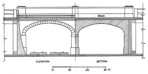
A TYPICAL EARLY double-
DURING the early development of railways in Britain earthworks were mainly adopted for the levelling out of the track both for economy and ultimate efficiency in preference to any form of bridge work. Bridges were, therefore, kept to an absolute minimum. Indeed it was considered a comparatively simple matter to employ gangs of men to construct earthworks as and where required in order to fill in low-
Improvements in the design of railway structures in general and bridge construction in particular soon led to the adoption of a greater number of bridges and viaducts than had otherwise been projected. Any shortage of spoil from a deep cutting along a line of railway did not deter engineers from following their set course. Indeed, in quite a number of schemes engineers found it more economical to bridge a valley with a brick viaduct than attempt to fill in the gap with thousands of cubic yards of loose material conveyed many miles to the site.
In the chapter on Brunel’s timber viaducts, it was noted that a grand total of 54 viaducts were constructed on the South Devon, Cornwall and West Cornwall Railways between Totnes and Penzance. It would have been impossible, of course, to bridge the 54 valleys and rivers with heavy earthworks and, to judge by the length and height of a number of the structures required, it can be readily understood why bricks, mortar and timber played such an important part in Isambard K. Brunel’s designs.
Possibly in no other projected railway scheme of the 1830’s was railway architecture given such careful attention as in the construction of the London and Birmingham Railway — later to form part of the L. & N.W.R. system.
The drawing at the top of this page shows a double-
The architect’s drawings show the foundations in detail and in one example the sections show stone blocks for supporting the rails, whereas timber sleepers had already been introduced for the permanent way.

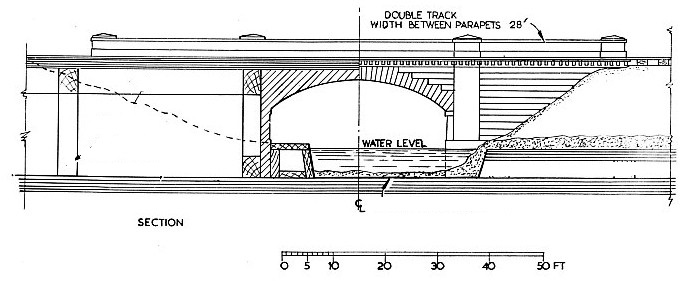
A TYPICAL EARLY railway bridge over a canal.
The drawing above shows a type of bridge built to carry a railway over a canal. A retaining wall is constructed on one side for the towpath below. In this example the railway is about 17 ft above the surrounding fields.
It was generally found that, owing to the unstable nature of the earth on such a site, it was necessary to provide deep foundations under the bridge abutments. It was therefore necessary to drive in a quantity of piles about 20 ft long. Over the head of these piles timber baulks were fixed and between them brick walling was built up. Over the whole area heavy planks were laid to form a raft for the base of the bridge abutments. The raft was then enclosed by timber piling with double timber wallings in order to give support to the whole mass. In this way the whole of the weight and thrust of the bridge could be spread over a large area.
On outdoor passenger-
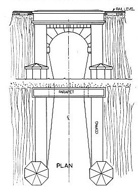
 An economy of bridge construction was effected in situations where it was necessary to provide a passage for cattle in open country. In carrying a double line of railway the continuity of a made-
A TYPICAL EARLY FIELD TUNNEL. The arch would be constructed of brick, with the stone portals and wing walls in faced stone. The decorative octagonal pedestals would have been constructed according to the situation. The wing walls were sometimes splayed outwards.
Large bridges could be adapted for any extent of embankment, but, if taken to a considerable height it was the practice to make the arch of extra thickness and also strengthen it with heavy tie bolts built into the crown of the arch from one end to the other. The diagram above shows details of a nine-
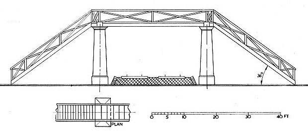
Even as early as 1840, passengers were being encouraged to cross the line by footbridges. In R. Macdonald-
The bridge is mounted on two substantial masonry columns each side of a double line of railway. Instead of turning both stairways at right angles, they lead in a straight path downward and away from the railway. Another interesting feature of the original drawing is the formation of the double line of railway below the bridge. Here again stone blocks are indicated and not sleepers.
Numerous other examples of bridge construction are given in Dempsey’s work of which only a few are noted here. Details are given of bridges on the Newcastle and North Shields, the Birmingham and Derby and for the Bricklayer’s Arms branch of the South Eastern Railway; likewise a number of well-
Whilst many of the early structures have been replaced by larger and heavier steel bridges designed to carry heavier and faster trains than those ever envisaged by their designers, some of the smaller structures are still extant. As G. Drysdale-

DESIGN FOR an early railway footbridge.
You can read more on “Brunel’s Timber Viaducts”, “Famous Viaducts” and “Over River and Lake” on this website.