
© Railway Wonders of the World 2012-


Over River and Lake
Railways That Span the World’s Waterways
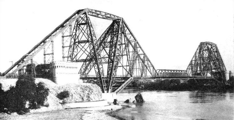
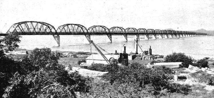
THE LANSDOWNE BRIDGE in India which carries the track of the North Western Railway across the River Indus at Sukkur. Built on the cantilever principle, the central span of 200 ft had to be floated into position. From the tower-
RECENT years have shown that the railway engineer is still as unafraid of the might of great rivers as in the days when he launched the Forth Bridge and first spanned the Falls of Niagara. His latest achievement in steel is the Lower Zambesi Bridge. This, the longest railway bridge in the world -
To do full justice to this great triumph in Africa demands in the writer an impossible combination of faculties -
Calling for a remarkable co-
The best river transport can never handle such large quantities of merchandise as the railway, and the lower reaches of the Zambesi are unfavourable for shipping. From December to March in each year the flooded river inundates the country for miles around. From August to November, on the other hand, it shrinks until it is so shallow that only flat-
At one time this river ferry provided the only link between the railway which ran south from Nyasaland to Chindio, on the north bank of the river, and the line which ran north from Beira to Murraca on the opposite bank. These two villages, Chindio and Murraca, are situated about ninety miles from the mouths of the Zambesi, and 160 miles from the Portuguese port of Beira, which lies to the south.
Since Beira is the only port which can conveniently handle the overseas trade of British Nyasaland, itself an inland territory, it will readily be seen how vital was the necessity for overcoming the break in the railway at the Zambesi River.
The building of the two-
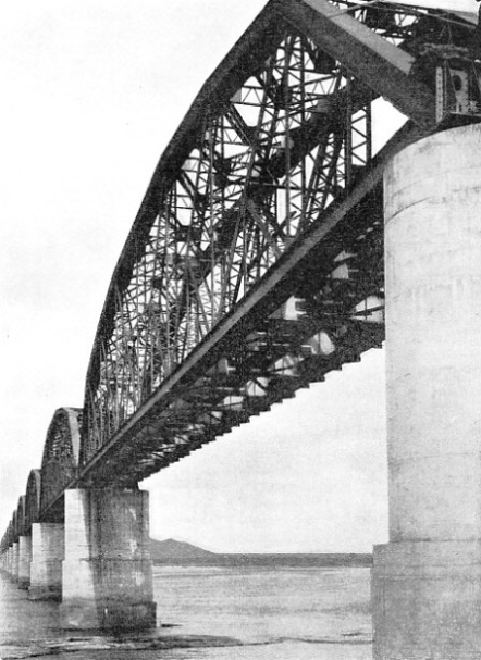
A CLOSE-
The preparations for the erection of the bridge included the construction of approach railway lines along new embankments, and the clearing of the bush to build a camp. The Cleveland Bridge and Engineering Co, Ltd, of Darlington. England, who secured the contract, placed orders for materials with nearly a hundred British firms. The necessary equipment included steel cranes, excavating gear, thousands of tons of steelwork, timber, cement, concrete mixers, diving apparatus, lubricating oil, electric light fittings, paint, machine tools, portable forges, scientific instruments, millions of bolts and nuts, medical equipment, water purification plant, portable offices, office furniture (specially treated to withstand the hot, damp climate), eight pontoons, twenty barges, and two light-
Some of the larger items, including the river barges, were dispatched in parts and reassembled on the banks of the Zambesi. Stone had to be obtained for concrete making; two quarries were opened for this purpose on either side of the river. To fit out the 2-
These supplies included twenty-
Not only did the engineers clear the bush to build a camp; they also changed the whole geography of the district and planted two small towns on opposing banks of the river. The European supervisors had four thousand native workers under their charge, at times even six thousand, and the task of housing, feeding -
World’s Longest Railway Bridge
 Exhaustive precautions were taken, with encouraging results, against the malaria peril. The perfection of the drainage system helped very largely in this direction, while a permanent gang of boys was employed to wage an anti-
Since the engineers and other Europeans had to spend four years in residence by the Zambesi, it was only reasonable that certain social amenities should be provided for their recreation during leisure hours. The indoor attractions comprised a recreation room, a squash-
This map shows the relative position of the Lower Zambesi Bridge
The remarkable preliminaries to the Lower Zambesi Bridge being completed, the year 1931 saw the beginning of construct-
There are several methods of achieving this difficult feat. The usual procedure is to erect a cofferdam, this being an arrangement for laying dry a space below water-
The earth cofferdam is the simplest kind, and is often used in shallow rivers with currents of low velocity. It consists of a bank of earth, containing a good deal of clay, placed round the pier foundation site to be enclosed, and of a thickness sufficient to furnish the required stability. The bank projects two or three feet above water, with a width of at least 3 ft at the top, though this width will probably be a good deal larger unless one or two strengthening rows of wood or steel sheet-
A more elaborate cofferdam is formed by driving into the river-
The engineers do not attempt to make coffer-
The nature of the Zambesi River permitted some of the pier foundations to be dredged without preliminary removal of the water, though cofferdams were usually adopted where rock replaced sand and mud at a distance not too great from the surface. Pontoons and barges, carrying concrete mixers, forges, cranes, and other impedimenta, were drawn round the site of each pier, forming suitable islands from which the constructional work could be conducted. During the dry season, as it happens, no water flows over the south side of the river-
The laying of the foundations began with the lowering of an oval steel curb, shaped like a steamer funnel, and with cross-
The well was built up in sections as the excavations deepened. At the same time it was filled with concrete, reinforced with vertical and horizontal steel rods. The two excavation shafts were, of course, not filled in till the sinking of the wells had been completed. The thirty-
The wells were surmounted by imposing concrete piers, likewise reinforced. Two additional main piers, bringing the total up to thirty-
The thirty-
From the right bank, or the Sena side of the river, the bridge is approached by a steel trestle viaduct, founded on ferro-
This, then, is the measure of the world's longest railway bridge, built at a cost of over £1,400,000. The provision of a footpath on the up-
The account which has been given of this engineering achievement will convey some idea of the complications and difficulties involved in the construction of major railway bridges in uncivilized territories.
It is a curious fact that the Lower Zambesi Bridge stands on a railway system which has a route mileage of only forty-
The Central Africa Railway, as it is called, is now operated by Nyasaland Railways Ltd, the company floated specially to finance the construction of the bridge. This company was empowered to purchase the Shire Highlands Railway, which ran from Port Herald to Blantyre, a distance of 113 miles, and to build an extension 160 miles long to Chipoka and Salima, at the foot of Lake Nyasa. An improved shipping service is being set up on this lake, which is 360 miles long. and a large part of Nyasaland will thus be brought within easy reach of the ocean port of Beira.
Although the bridge at Sena has not yet had time to enlarge the fame of the Zambesi River on its own account, this great African waterway has long been associated with one of the most spectacular engineering triumphs in the world. This is the well-
Taming the Nile
The bridge is 650 ft long, the main span accounting for 500 ft, with the furious waters seething 400 ft below. The work reached completion in 1904, two years alter Cecil Rhodes’s death. It represents a paramount link in the railway which this great statesman hoped would one day run from the Nile Delta to Capetown -
The “taming of the Nile” is a favourite occupation with engineers, and probably another century will pass before the world’s longest river has been bridged and dammed a sufficient number of times to satisfy all concerned.
The latest railway bridge across the Nile is in Uganda, near Jinja, a town standing on the north shore of Lake Victoria, a source of the river. Communication was previously maintained by a ferry which ran across the head of the lake a little above where the Nile rises. But when the Kenya and Uganda Railway decided to extend its main line westwards from Jinja to Kampala, the commercial capital of Uganda, the construction of a bridge over the Nile became imperative.
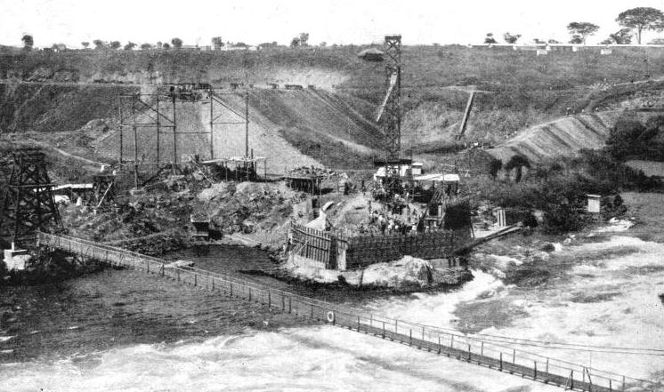
BUILDING THE JINJA BRIDGE for rail and road across the Nile, in Uganda. Approach embankments are shown in course of erection, and the foundations are being laid for the masonry pier, which will receive the east end of the main arch. A temporary foot bridge, complete with life belt, was thrown across the river, and can be seen in the foreground.
The railway extension began on January 1, 1929, and the bridge was opened for traffic on January 14, 1931. The single spandrel-
Unenlightened townsfolk of Jinja may have viewed with indignation the new bridge which the engineers began to put up when they first arrived. But this was only a temporary footbridge erected to provide easy communication between the two river banks during the construction of the main bridge; the swirling waters made the use of boats dangerous. The cost of the Jinja rail and road bridge came to approximately £70,000.
One child in every five is born in India; and a territory so densely populated as this requires an elaborate railway system, to serve its needs. The abundance of rivers in India gives engineers many opportunities for testing their bridge-
One of India’s most famous bridges -
Notable Indian Bridges
The Victoria Falls Bridge also was built on the cantilever principle, but nothing more dissimilar to the Lansdowne Bridge could be found than the graceful arch spanning the Zambesi Gorge. The Indian bridge has a clear span of 790 ft from tower centres -
Of the many hundreds of railway bridges to be found in India, some are of notable length. These include the Upper Sone Bridge, 10,052 ft, on the East Indian Railway; the Lower Godavari Bridge, 9,096 ft, on the Madras and Southern Mahratta Railway; and the Mahanadi Bridge, 6,912 ft on the Bengal Nagpur Railway. These mammoth bridges are carried in some part over land, and their continuous length over water is not so great as that of the Lower Zambesi Bridge.
Another great Indian bridge, opened by Lord Willingdon, the Viceroy, in December, 1931, spans the River Hooghly at Bally, near Calcutta. The Willingdon Bridge, as it is called, involved the use of 17,000 tons of steel, and cost nearly £3,700,000 to build. The steelwork was made at Calcutta. The seven giant 350-
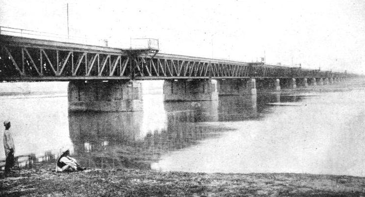
A NOTABLE INDIAN BRIDGE is the road and rail bridge at Jhelum across the river of that name, on the North Western Railway. There are fifty spans of 94 ft 6-
The Willingdon Bridge offers a new outlet for Calcutta’s trade with Bengal and other provinces.
The Kistna Bridge in Hyderabad, on H.E.H. the Nizam’s State Railway, is typical of a large number of medium-
Though much of H.E.H. the Nizam’s State Railway is laid to the broad 5 ft 6-
The erection of these 80-
After the span had been secured in position it was an easy matter to lay the rails upon the waiting sleepers, and the travelling derrick could thus proceed with the second span and lower it to reach the third pier. In this way the thirty-
The seemingly precarious nature of the railway over the Kistna Bridge is not unusual, as a corresponding arrangement is sometimes found with bridges and viaducts of different designs in England. If it is the opposite of reassuring to cross one of these narrow, open-
I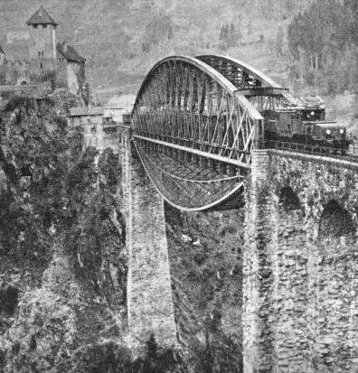 n extending praises to those who endanger themselves in the work of building railway bridges, it must be mentioned that a wire netting is sometimes stretched beneath a new span while construction proceeds. But this only partly amends the situation; the sensation of dizziness still prevails, and it requires the skill of a trapeze artist to be sure of avoiding injury should a fall into the net occur.
AN IMPOSING AUSTRIAN BRIDGE which takes the railway across the Trisanna Gorge in the Tirol. To carry the heavy electric locomotives now used over the Zurich-
The traveller by train from Zurich to Innsbruck travels through the six and a half miles Arlberg Tunnel, in the Austrian Tirol. Beyond this the line to Innsbruck is confronted with the Trisanna River, at a point not far above its confluence with the Rosanna.
It is refreshing to find how often the engineer, when called upon to design an instrument of utility, achieves a master-
To strengthen the bridge sufficiently to carry the modern electric locomotives and international rolling-
The weight which a new or rebuilt bridge can bear with safety is, naturally, known theoretically in advance, but practical tests with abnormally heavy burdens are made in addition, only the very smallest bridges being exempt from this precaution. The Sydney Harbour Bridge affords an example of the thoroughness with which testing is carried out. Before the bridge was opened to traffic, scores of locomotives were run on to all four railway, tracks, until these were packed solid from end to end. The locomotives weighed 4,000 tons -
The coming of the Sydney Harbour Bridge robbed another New South Wales bridge of premier Australian fame. Fifty years ago, the estuary of the Hawkesbury River, between Newcastle and Sydney, alone remained to be conquered so as to complete a continuous chain of railways traversing four colonies and extending from Oodnadatta in South Australia to Cunnamulla in Queensland, a distance of 3,100 miles. On May 1, 1889, the Hawkesbury River Bridge was opened, the work having been carried out at a cost of £340,000 by American engineers, using English materials.
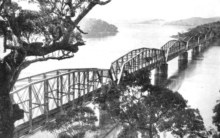
A FAMOUS AUSTRALIAN BRIDGE which spans the estuary or the Hawkesbury River in New South Wales. The bridge was opened in 1889 and cost £340,000. It has seven 416 ft spans, and every day the “Brisbane Limited” crosses the bridge on its journey between Sydney and Brisbane.
The inequalities of the bed of the estuary were such that, while some of the pier foundations were only just over 100 ft in depth, yet in one instance a steel cylinder 150 ft in height had to be sunk into the soft mud, for filling with concrete. The seven 416-
Across the Great Salt Lake
Some of the wildest and most picturesque scenery in the world lies in North Queensland. Not far from Cairns, by the Pacific coast, the railway passenger is carried through the heart of one of the most cherished beauty spots, thanks to the bridge installed beneath Stony Creek Falls. This is a graceful structure built on a curve, with the 150-
Much has been written about wonderful bridges in the New World.
When the Union Pacific Railway pioneers were laying their trail westwards towards San Francisco, they found their line of progress impeded by the Great Salt Lake. To save expense and time, they carried their line round the obstruction. But the gradients and sharp curves involved high running costs, and a short cut of thirty-
The short cut across the Great Salt Lake saved the Union Pacific nearly forty-
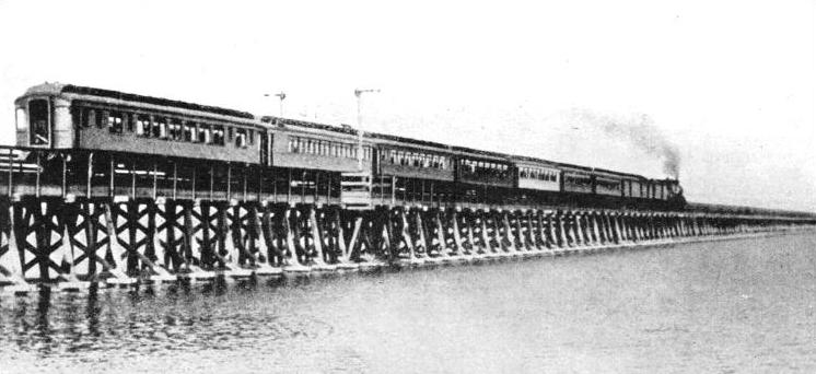
A SOUTHERN PACIFIC RAILWAY EXPRESS crossing the Great Salt Lake Utah. The lake is 31½ miles across, and the trestle bridge and embankments cost £1,000,000 to build.
The Trans-
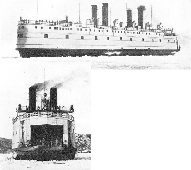 THE BAIKAL, a gigantic ice-
STERN of the Baikal. Above the train deck the ship provided comfortable accommodation for 150 passengers. The feat of transporting the vessel in sections across 4,500 miles of land to the heart of Siberia is an outstanding one in the annals of engineering.
Although Lake Baikal is only some forty miles wide at its southern portion, it is 397 miles long and many thousands of feet deep. Fierce storms frequently pile up waves 6 ft high. This in itself would not be an appreciable obstacle to a well-
These features were successfully combined in a masterly ship, perhaps the most singular train ferry of all time. Messrs. Sir W. G. Armstrong Whitworth & Co, Ltd, received their order in 1896, and the vessel was constructed on the sectional principle at their Elswick Works, taken to pieces and packed on board an ocean steamer in less than six months. The conveyance of the 7,000 packages over 4,500 miles of land from St. Petersburg -
The parts of the Baikal as the ship was appropriately christened, were transported in wagons to Krasnoyarsk, which at that time marked the eastern limit of the Trans-
An Ingenious Ice-
In view of the primitive methods of transport available, it is not altogether surprising that the time taken to carry the dismantled Baikal from St. Petersburg to the great lake was two years and three months. The English engineers, sent out to accompany the vessel on the last critical stage of the journey and to superintend erection, were confronted with a certain amount of chaos when they arrived. Many were the occasions when they longed in vain for the equipment of a Newcastle shipyard and for the skilled men to be found in that distant region The Russian workmen at last completed the task of erecting the ship, and a miracle of man’s invention was launched upon the lake.
The main features of the completed Baikal proved no less interesting than the events which led up to her making. The overall length was 290 ft, beam 57 ft, and displacement 4,250 tons. Twin engines, each of 1,250 horse-
The train deck of the Baikal had a capacity for twenty-
THE WORLD'S LONGEST RAILWAY BRIDGE -
You can read more on “The Forth Bridge”, “Some Wonder Bridges” and “Sydney Harbour Bridge” on this website.
You can read more on “Bridging the St Lawrence”, “Building the Menai Bridges” and
“Story of the Tay Bridges” in Wonders of World Engineering.