
© Railway Wonders of the World 2012-


Sydney Harbour Bridge
One of the World’s Greatest Railway Links
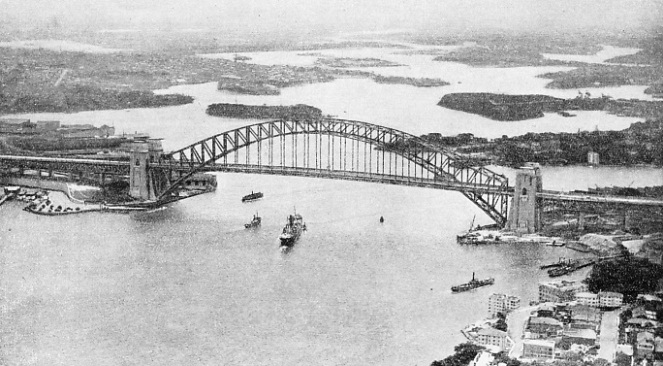
CROSSING SYDNEY HARBOUR in a single span of 1,650 ft between the centres of the hinges, at a clear height of 170 ft above the water, this bridge carries rails, road, and footways, the total width being 160 ft. The arch span, which rises to a height of 440 ft, is flanked by massive masonry pylons, with five steel approach spans on either side of the harbour. The contract was let in March, 1924, the two halves of the main span met in August, 1930, and the bridge opened to traffic in March, 1932.
THE bridge spanning Sydney Harbour -
As early as 1815 a suggestion for the bridging of Sydney Harbour was submitted to the Government, and the subject was raised at intervals throughout the remainder of the last century. By 1900 development in and around Sydney had made enormous progress, and in that year the New South Wales Government invited competitive designs for a bridge. Numerous proposals were made but no contract was placed. During 1911-
As a railway link, of course, the bridge was of paramount importance, not only to join the northern suburbs with the City, but also to unite the lines north of Sydney with those serving the eastern, western and southern suburbs. With the Pacific Ocean to the east and very important docks to the west of its position, it was likewise imperative that the bridge should provide unimpeded passage for the largest ships.
In January, 1923, tenders were invited for the building of a bridge, the layout and span of which were defined by the Government’s engineer, Dr. J. C, C. Bradfield, There was keen competition to secure the contract. It was eventually awarded by the New South Wales Government in March, 1924, to a British firm, Dorman Long & Co, Ltd, of Middlesbrough. A note of regret echoes in the story of the contract. The decision to tender for the construction was due to the late Sir Arthur Dorman and the late Sir Hugh Bell, and the successful completion of the bridge was in no small measure due to their initiative and advice. They lived to see the arch finished but were not spared to see the completion of the bridge.
Mr. Ralph Freeman, consulting engineer to Dorman Long & Co, prepared designs for three different types of bridge; the arch actually built, a cantilever arch and a cantilever bridge. Alternative combinations of these types, with and without pylons, necessitated the preparation of seven different projects. The design chosen by the Government was the Company’s tender for an arch bridge with granite piers and granite pylons, to cost £4,217,721. The architectural features of the masonry conformed to the designs of Sir John Burnet and Partners.
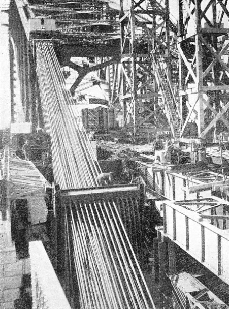
ANCHORAGE ROPES being dismantled at the South Pylon after the closing of the main arch. The arch was erected by building out the two half-
The whole of the steel used -
The weight of steel involved in the contract was 51,000 tons, of which 38,000 tons are in the arch. Most of this great mass of metal was shipped to the bridge site from Middlesbrough -
Weight alone called for the most exacting accuracy in calculating the proportions of the various girders and components, and the provision of massive foundations deep in the solid rock of the harbour shore. The effect of the wind on so large an area had to be countered by a system of cross-
Heat and cold were factors that required the most careful consideration. These factors -
The loads specified in the contract for these trackways give some idea of the service demanded of the bridge. The footways have had to be capable of supporting a load of 100 lb per square foot of their surface. The roadway had to carry a motor lorry (12 ft by 6 ft wheelbase) occupying a space of 30 ft by 12 ft in any position. The front axle load was not to exceed 18,000 lb, and that of the back axle, 36,000 lb. The remainder of the roadway load was to be 100 lb per sq ft. Requirements for the railway load were for the support on each track of two locomotives, each 65 ft long and weighing 360,000 lb, followed by a train weighing 2,200 lb per ft of its length.
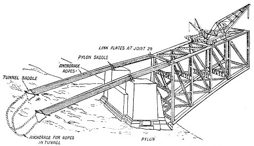
THE TUNNELS for the rope anchorage at either end were driven into rock at an angle of about 45° to the horizontal. The lowest point was some 100 ft below the surface, and the peculiar shape rendered excavation difficult. Spoil was removed by skips running on narrow gauge inclines. The skips were hauled by an electric winch. To provide a seating for ropes throughout their bearing on the face of the rock tunnel it was necessary to form a suitable surface. This was achieved by setting up specially corrugated sheets bent to the true curve and backed with concrete. DIAGRAM SHOWING METHOD OF ROPE ANCHORAGE during the erection of the two half-
We have already outlined the principal dimensions of the bridge, but the following particulars give an indication of the arrangements and massive proportions of the component parts. The arch is composed of four main members, rising from the hinges to which we referred earlier, and the topmost pair comprise what is known as the “upper chord”. The under pair, much larger and heavier in section, form the “lower chord”. The chords are joined by vertical girders or “trusses” forming twenty-
The hinges are 27 ft 6-
The lower chord, resembling three very long rectangular steel boxes placed side by side, varies in depth from 4 ft at the centre of the arch to 8 ft 3-
Apart from the increased depth of the web plates which has been referred to, the section of the chord members was enlarged by adding side plates and by increasing the thickness of the flange plates forming the central portion of the I’s.
The upper chord has a constant depth of 3 ft 4-
The four bearings that carry, through the hinges, the whole weight of the bridge, each withstands a pressure of 19,700 tons. The bearings are inclined at an angle of 45 degrees to the horizontal, and rest on immense concrete foundations laid on the solid rock. This part of the work will be described later.
The pressure from the lower chord of the arch is received on an upper saddle of forged steel resting on a pin 14½-
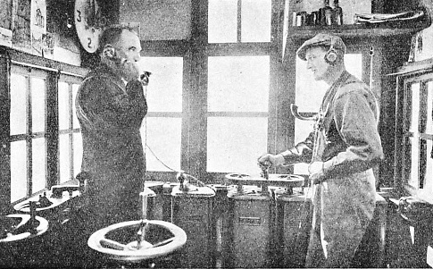
THE CONTROL CABIN of one of the giant creeper cranes. The crane drivers were given orders by telephone from officials working some 400 ft below. When erecting the bridge each crane travelled forward on the top chords of the structure, and in each new position built up another part of the bridge in front of itself. The cranes were first tested in England.
The main web plates are connected together by ten transverse cast steel diaphragms. The lower edges of the web plates rest on six steel base castings interlocked and fitted together, machined below and on the bearing faces. The lower forged saddle, web plates, diaphragms and base castings are all interconnected with fitted 4-
The manufacturers and contractors had other views, however. The main components of the bearings were fitted to a limit of error of 1-
The vertical trusses or end posts, rising from the bearings at either end of the bridge, are of immense size -
The deck, in addition to the support of cross girders at the end posts, is also carried on cross girders attached to the vertical trusses of the first three panels at either bridge-
The construction of the deck and the ingenious method of carrying the railway tracks are especially interesting.
The deck comprises longitudinal members, known as “stringers”, connected by cross girders and strengthened by diagonal cross bracing. The heaviest loads upon the bridge are, of course, the trains running on the four railway tracks; for this reason these are laid on either side of the hangers on both sides of the structure. One railway track on either side of the bridge is thus outside the great arch; beyond these are the footways. They are surfaced with asphalt on a foundation of breeze concrete laid on steel troughs. The steel troughing is carried by close-
Between the inner railway tracks is the 57 ft roadway, surfaced with asphalt on a foundation of coke concrete. This light-
An interesting addition to the deck structure is the system of latticed girder stringers of box form under the centre lines of the arch trusses between the inner railway tracks. These stringers, the full length of the suspended portion of the deck, form runways; beneath these runways are supported the “travellers” required for inspection and painting of the underside of the deck.
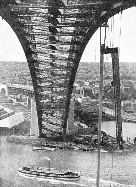 The hangers from the arch supporting the deck vary in length from 20 ft to 190 ft at the centre of the bridge. These members are of box section open on two sides and built up of channel-
A SPECIAL TILTING CRADLE was used to lift the hangers as one piece into their positions on the main arch. The heavy steel cradle supporting the hanger was hauled up horizontally at first, and then tilted with its load in mid-
The lower ends of the hangers pass between the webs of the deck cross girders to which they are connected by 14-
Expansion joints are provided the full width of the roadway, and consist of a series of interlocking steel bars attached alternately to either side of the gap -
The approaches to the bridge are in keeping with the rest of the structure and consist of massive side girders, carrying the deck, supported on granite-
On the South side (Davies Point), the construction is similar to that on the North, except that the approach is straight and the span at the extreme south end is 238 ft instead of 170 ft, on account of an existing road crossing.
The most spectacular masonry work of the structure is to be seen in the immense pylons nearly 300 ft high; these not only form impressive entrances to the central span from the approaches, but they also satisfy the eye in forming an apparent support to the thrust of the arch. Set in the middle of the wonderful natural beauty of Sydney Harbour, these pylons are in keeping with their surroundings. Their architectural treatment lies to the credit of Sir John Burnet and Partners, of London. As structures, the pylons are among the largest yet built in concrete, and involved special problems in design and construction, regarding which the contractors consulted Dr. Oscar Faber, OBE, Minstce.
Solid rock forms the foundation for the pylons, and so thick are the wall bases that pressures are small and the foundations required no special preparations. The area covered by each pylon at ground level is 160 ft by 230 ft. The lower part of each pylon up to the bridge deck level forms a single tower, and above this the structure is continued upwards in the form of two towers, one on either side of the bridge. The twin towers are pierced longitudinally by archways each carrying one footway and one railway track. The two inner tracks and the roadway run in the space between the towers. A roof of reinforced concrete covers each tower, and the outer walls are stiffened by reinforced concrete floors. In the interiors of the towers are steel staircases that give access from ground level to the top.
It is below the front wall of the pylons that excavations were made for the foundations of the arch bearings -
Workshops in which the construction of the steelwork was carried out were built near the bridge site at Milsons Point. These shops were divided into two departments -
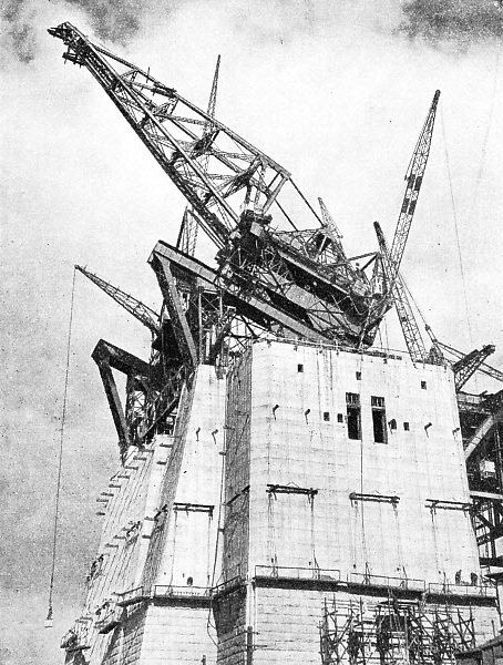
AN INCOMPLETE PYLON. The height of the finished pylons above water level is 285 ft. For building the walls of the pylon structure up to deck level of the bridge -
The “heavy” shop was designed for the construction of the members and the arch trusses. Some of these were of unprecedented dimensions. The shop was 500 ft long and 147 ft wide and was equipped with two 120-
The entire plant and tools with which these shops were equipped were supplied by British manufacturers, and the total cost of the workshops, and the site-
Included in the plant was a flat-
The machines in these workshops were of a remarkable character. That used for planing the edges of steel plates had a capacity up to a length of 66 ft and a thickness of 2¼-
High-
For shearing plates and cutting angles to length special machines were provided capable of “snipping off” pieces of steel up to the maximum thickness of 2¼-
Drilling was carried out by a battery of fifty-
A particularly interesting type of drilling machine employed was of the gantry type travelling on a track 13 ft wide on the shop floor. These machines each comprised a massive carriage on wheels, carrying a pair of radial drills capable of drilling holes at any point in an area 12 ft wide by 150 ft long. Nine of these machines were installed, and several of them were placed on the same length of track for simultaneous drilling of the long pieces.
The rivets used for the principal connexions of the structure were of a diameter greater than is generally used even in heavy bridge work. The largest rivets in the bridge are of 1⅜-
All riveting on the bridge site was done by pneumatic hammers. Riveting in the shops was carried out by hydraulic riveters as far as possible, but the closed box form of the members necessitated the use of pneumatic hammers for shop rivets also. The rivet holes were drilled 1/32-
For finishing to correct length or “ending” the chord sections of the arch a Hulse wall planing machine was employed. This machine, believed to be the largest of its kind ever employed on structural work, was capable of dealing with a surface 12 ft by 10 ft.
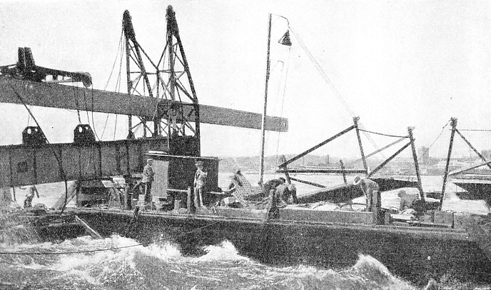
A VIOLENT GALE delayed the erection of the first hanger in September, 1930. The hanger, for the support of the main deck, was towed out into the harbour ready for lifting into position, but was caught by a fierce gale and nearly lost. The setting of the hangers presented the engineers with one of the most difficult problems of the bridge.
The planer, despite its size, was capable of an amazing degree of accuracy in the important work on the chord members. It was upon the accuracy of the fitting of chord members, more than any other process, that the final accuracy of the complete structure depended.
After the ending operations on the chord members, the group of members meeting at every panel point was assembled on the floor of the shop, and all rivet holes were reamered to size.
All the principal members of the arch and deck system were fitted with specially designed lifting gear and brackets to facilitate erection. No rope or chain slings were used.
The entire plant and machinery in the shops was electrically driven. Alternating current, 440 volts, 3 phase, 25 cycles, was used for power purposes, and 240 volts for general lighting.
The granite for the piers and pylons was obtained from a quarry provided by the New South Wales Government at Moruya on the coast about 150 miles south of Sydney. The quarry was equipped with the necessary machinery and a wharf. Many of the men were recruited at Aberdeen and sent out to Australia for this work. A small township was built to accommodate the quarrymen and their families. The buildings included a stores, post office, assembly hall and school. Throughout 1925 to 1931 the number of men employed at the quarry was about 240.
The plant and machinery for the quarry was sent out from England, and consisted of four locomotive-
Giant Testing-
For the transport of granite and crushed stone to Sydney, Dorman Long had three single-
In the steel-
No risks were taken with so immense a structure as Sydney Harbour Bridge, and an Avery testing machine of 1,250 tons capacity was built to test to destruction large scale models of various parts of the bridge structure.
The first stage in the building of the bridge was the erection of the approach spans and other works on the shores of the harbour. Timber wharves were constructed adjacent to the centre line of the bridge on the Dawes Point and Milsons Point abutments. Plant and materials required for building the approach spans were hauled up specially constructed inclines 1,300 ft long, provided with standard gauge railway track. The inclines were operated by 10-
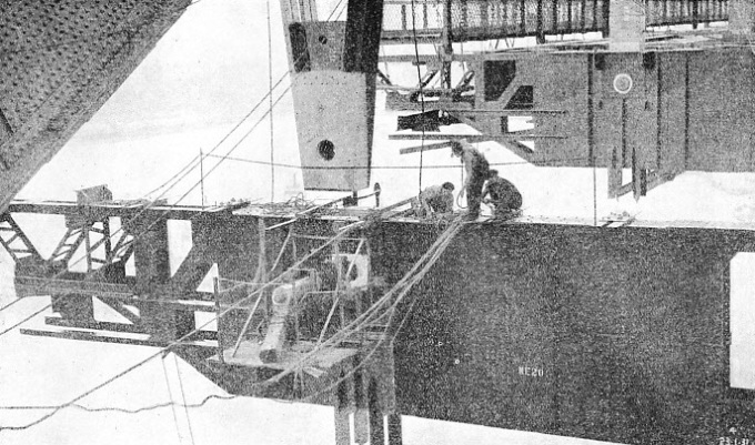
CONSTRUCTION WORK IN MID-
Work on the southern approaches was begun first, as the construction site for the north approach was not available for some months later. A 7-
To enable the construction of the approach span steelwork to be accomplished, two lines of wooden towers, known as “falsework” were built on either side of the bridge centre line. The falsework was constructed of 12 by 12-
The falsework carried the weight of the approach spans as they were built up panel by panel, and the timbering also supported a gantry track with an 80 ft steel traveller used in erecting the cross-
The riveting of the first span was completed while erection was proceeding with the second. The falsework of the first span was then re-
The construction of foundations for the arch bearings was an undertaking of great magnitude. Excavations for the four bearings were each 90 ft long, 40 ft wide and approximately 40 ft deep. About 50 ft of rock separated the excavations from the water in the harbour, and special walls and coffer dams were constructed to prevent the ingress of water. Every care was taken to ensure that the rock below the excavations was sound. The thrust of the foundations was computed at
13 tons on every square foot of rock. To test the foundation site a number of borings were made with a hollow diamond drill to a depth of 75 ft in the solid rock. On examination of the “cores” taken from the drill it was found that below the excavations the rock was reliable sandstone without cracks or fissures.
The concrete filling, consisting of four parts crushed granite, two parts sand and one part cement, was mixed in a power-
The walls of the great pylons are founded on solid rock behind the main bearings, and are of concrete placed between interior timber “shuttering” and the outer granite facing. The facing at the lower levels of the pylons is of very large granite blocks weighing between 5 and 9 tons. The thickness of the pylon walls above a level taken at 27 ft 6-
For building the walls of the pylons up to deck level, 155 ft above the base, two 7-
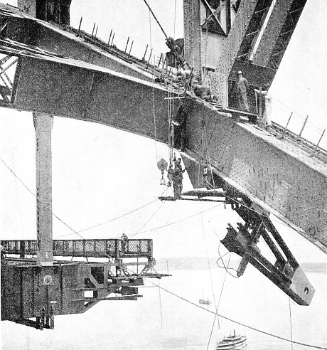
51,000 TONS OF STEEL were absorbed in the construction of the bridge, and 38,000 tons of the total went in the building of the arch. All the steel used -
By the time construction had reached a height of 155 ft the approach span steelwork was completed as far as the pylons, and steelwork for carrying the roadway and railway tracks over the pylon towers was placed in position. Construction of the pylons was suspended at this stage during the erection of the arch span. The placing of the granite facing, however, was continued, and was completed to deck-
The triple functions of the great hinge-
Two independent base lines were accordingly set out on the North shore at an angle of about 117° to the bridge centre line, each about 1,200 ft long and close to one another, but not parallel. Two independent surveys, using these base lines, were then carried out, and two fixed points were determined, one on either side of the harbour, adjacent to the pylons. A micro-
Each of the four bearings weighs 300 tons, and is secured by two rows of twelve 4½-
The building of the bridge, from either side of the harbour simultaneously, was accomplished by two special “creeper” cranes that were moved forward over the top chords of the arch as work proceeded. Either of these cranes, weighing nearly 600 tons, comprised in itself a number of subsidiary machines for special purposes. The main crane was supported on a rectangular steel framework 148 ft wide, carried on four four-
The main hoist at the end of the 105 ft jib was operated by two 120 hp electric motors capable of lifting a load of 120 tons. The jib was moved up or down by 9-
The main traversing carriage also carried two 2½-
The creeper cranes were erected by the 25-
In September, 1928, the erection of the southern arch trusses was begun. The creeper crane was erected on a steel “ramp” on the pylon, ready for transfer to the upper arch chords when completed.
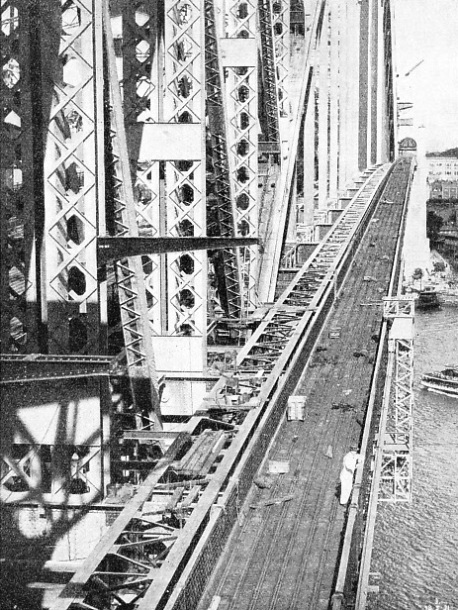
PEDESTRIAN TRAFFIC is catered for on the Sydney Harbour Bridge by two 10 ft wide footways, one of which is seen above. The bridge has a roadway in the centre of the bridge 57 ft wide, and the four railway tracks -
The first portions of the arch to be placed in position were the lowest sections of the lower chord. The end posts, 190 ft long and weighing 70 tons each, were then erected, and supported temporarily by struts from the pylon walls. The end posts were sloped backwards against the wall struts to ensure a gap between the half arches, at the centre, until the time for the final uniting of the arch. Before the first panel could be completed from the end posts it was necessary that these should be secured rigidly against their wall struts to prevent any tendency to “topple” forward into the water.
The end posts were anchored during the building of the arch by 128 steel wire ropes, each 2¾-
The south tunnel was 133 ft long, 25 ft high, and 7 ft wide, with the floor some 100 ft below ground level. The north tunnel was approximately of the same dimensions except tor the length, which, on account of the curvature of the approach, was 170 ft. Both tunnels were lined with concrete, and faced with corrugated steel sheeting shaped to the required curvature. To guide the ropes, special saddles were constructed of reinforced concrete 30 ft long, 10 ft wide, and 30 ft high, pierced by 128 steel tubes, 5-
For the building of the first panel of the arch it was necessary to provide a preliminary anchorage, consisting of eight ropes. After the transfer of the creeper crane from the ramp joining the pylon to the top of the first panel, it was possible to attach the main anchorage ropes. Erection of the panels -
When the two halves of the arch had been finished, the anchorage ropes were lengthened or “paid out” by special hydraulic and screw gear to enable the lower chords to meet in the centre. Each of the steel ropes was lengthened separately, and the whole process of lowering the half-
The joints between the lower chords at the top of the arch comprised hinge bearings with 8 in diameter steel pins.
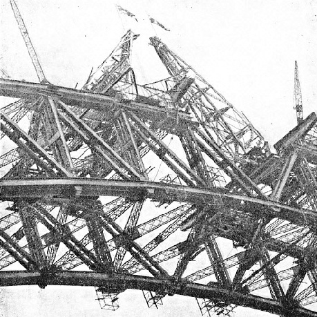
FLAGS WERE FLOWN on the creeper cranes to denote the permanent closing of the lower chords of the arch. The joining of the two completed halves of the great bridge was accomplished by the lengthening of the anchorage ropes. The two creeper cranes weighed each nearly 600 tons, and the main hoists were capable of raising 120 tons at 12½ ft per minute. They were specially designed for this particular construction, as was much of the other equipment.
So that correct alinement could be obtained, the outer ends of the south half-
The arch-
At this stage all stress at the arch crown was in the lower chords, so that on completion of the upper chords they also had to be subjected to a compression stress. This was necessary to make the completed arch into an absolutely rigid structure resting only on the main bearings at its feet. Accordingly the upper chords were forced apart by hydraulic jacks exerting a pressure of 3,250 tons. Carefully machined steel slabs were then inserted in the gaps between the upper chord members, so completing the arch.
Immediately the arch was finished the creeper cranes began their return journey, building the deck structure as they moved back to the pylons. The cross girders of the deck, 160 ft long and weighing 110 tons each, were floated out under the arch on a pontoon. The girders were lifted off the pontoon by the creeper cranes, and suspended from the lower chord of the arch by hangers. In pictures of the bridge, these hangers, dwarfed by the gigantic arch, appear as mere threads. In fact, however, they are of enormous proportions -
Sydney Harbour bridge was formally opened on March 19, 1932.
For the additional illustrations in the photogravure supplement, use this link.
You can read more on “Across Australia by Train”, “Marvels of Engineering” and “Travel in Australia” on this website.
You can read more on Spanning Sydney Harbour in Wonders of World Engineering