© Railway Wonders of the World 2024 | Contents | Site Map | Contact Us | Cookie Policy


Railway Signalling
The Development of Signalling on Britain’s Railways

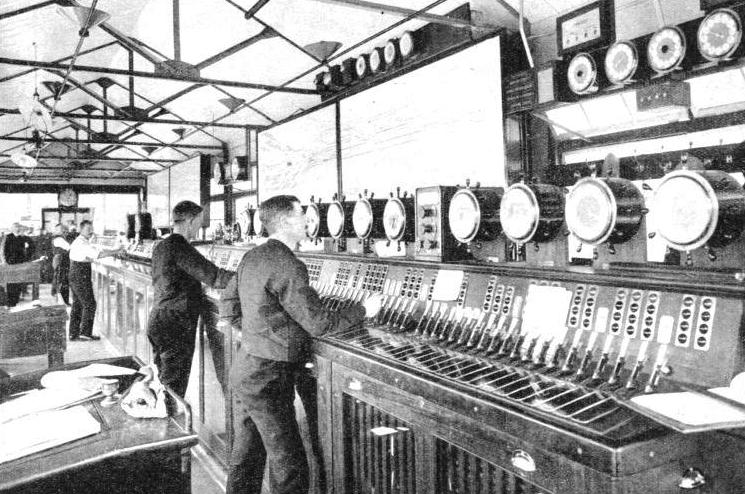
LONDON BRIDGE SIGNAL-
THE railways of Britain are guarded by signal cabins spaced at least every five miles and on lines with heavy traffic, particularly in the vicinity of large stations and junctions, the cabins are sometimes within a few hundred yards of each other. Pulling and pushing the heavy signal and point levers for 12 hours or more at a stretch is arduous.
Signals in the very early days of the railway generally were given by flags, lanterns and hand and arm signals. “Policemen” stationed at intervals alongside the track were responsible for the safety of trains by signalling the time which had elapsed since the preceding train had passed his position. For many years in Britain signalmen were called “Bobbies” because their original duty was to police the line. However, the first passenger steam railway, the Liverpool and Manchester, installed rotating “disc” signals within four years of its opening in 1830 and on the London & South Western Railway disc signals were introduced in 1840.
As train speeds increased it was found that a man with a flag or lantern standing at track level could not be seen in time by the driver of an approaching train and means were sought to improve signalling by erecting rotatable masts with shaped boards. Although the boards were not all disc-
One alternative tried in 1840, but not perpetuated in Britain, was a ball hoisted to the top of a mast to indicate when the line was clear. In North America this type of signal was used for many years and from its use came the expression “highball” to indicate “proceed”.
Brunel’s Great Western disc-
The “discs” on rotatable posts were gradually superseded by the semaphore signals which were to become a distinctive feature of British railways. The first semaphore signal, supposedly derived from the signal arms used by ships of the Royal Navy (but more likely derived from the Chappe land relay chain) was installed by C. H. Gregory on the London and Croydon Railway in 1841. At first the semaphore arms could be set to three different positions: the arm horizontal to indicate “stop”; at 45 degrees to show “caution” and vertical, concealed in the slotted post, “all clear”. Although in general these indications, or aspects, replicated the displaced policemen’s arm signals, there was little standardisation between individual railways, nor indeed any need for it in early years, of signal aspects and their interpretation.

Station post signal of c.1844 set at caution and danger.
An essential part of a signalling system is communication between signal cabins. Despatching trains on the time-
Around 1850 there was significant progress in block telegraph systems, notably by Edward Tyer who simplified the equipment and reduced the number of wires and batteries required to operate it. He also anticipated the modern track-
In 1861 he invented the step-
The single-
During the 1870s more and more signal and point levers were being concentrated in frames at one point so that they could be interlocked with each other to prevent the signalmen displaying signals which conflicted with the position of the points. Instead of signalmen who operated the signal levers and pointsmen who stood at the point levers beside the track, all were brought under the control of one man in a signal cabin. This became the standard British arrangement and one which was encouraged by legislation administered by the Board of Trade. It was not, however, adopted in other parts of the world even when there were traffic conditions sometimes as complicated as those of this country.
In the 1890s the three-
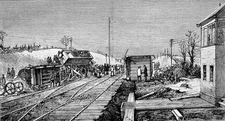
In Britain the lesson was learned early enough. At Abbots Ripton in 1876 the signalman acted correctly and set the signals for the trains passing through his section. In driving snow and freezing air temperature, the southbound “Flying Scotsman” was rapidly overhauling a slow freight train on the same line. Blinded by snow, the driver of the freight overran the stop signals at Holme, where the signalman intended to shunt the freight into a siding out of the way of the Scotsman, which was only 16 minutes away. It was not until the freight train had run past two more signal cabins, which were not on the telegraph line and therefore were unaware of the developing situation, that the signalman at Abbots Ripton, advised by the telegraph, stopped the train and instructed its driver to back into the siding.
The signalman to the north of Abbots Ripton had correctly set his signals to danger behind the departing freight train and would keep them “on” until he received the bell code, “train out of section” from Abbots Ripton. Within a few minutes the block bell told him that the Scotsman was approaching his signals. To his surprise it did not slacken speed but swept past and disappeared to the south, lost in the swirling snow. At Abbots Ripton it crashed into the side of the freight train which had not completely cleared the main line. The driver of the express had seemingly ignored the distant signal for Abbots Ripton; the lever for which and that for the home signal were both in the “on” position. The disaster was worsened because of poor communications and the appalling weather conditions, which prevented a northbound express from being stopped before it crashed into the wreckage.
The driver of the “Flying Scotsman” had been lured into danger by signals giving a false indication that the line was clear. The signalmen concerned had acted correctly but the signal arms were frozen in the clear position by snow packed in the slots in which the arms moved. The balance weights designed to pull the arm to the stop position in the event of a broken wire could not overcome the resistance of the frozen arm and the pull of wires weighed down by frozen snow.
Abbots Ripton highlighted inadequacies in the signals and their equipment of the 1870s and the difficulties of drivers and signalmen working in adverse conditions. However, as has happened before and since, the report of the Board of Trade Inspector on the accident contained recommendations intended not only to avoid a recurrence but to improve the safety of the railways generally. Among them was the abandonment of the type of semaphore signal which fell to “clear” into a slot in the signal post.

The railway accident at Abbot’s Ripton. The scene on the line after the double collision.
Even more important however was the abandonment of the principle of keeping signals normally in the “off” position and putting them to “danger” after a train had passed. Instead, in British railway practice, the signals were to remain normally in the “on” position and were to be cleared only after the necessary bell signals had been exchanged and the line proved clear.
Had that been the practice at Abbots Ripton then the signal arms might have frozen in the danger position which, while inconveniencing operations, would have been a “fail-
Safety of train movements had been the subject of a number of Governmental regulations which were introduced successively from 1839 onward. The Board of Trade and its inspectors were empowered to investigate operating practices and the provision of satisfactory methods and equipment for the safety of railway passengers. However, it was in the Railway Regulations Act of 1889 that the Board of Trade finally consolidated and codified regulations and orders applying to all British railways. The regulation covered the adoption of the absolute block system of working for all passenger lines, ie one train only in a section at a time; the interlocking of all points and signals on passenger lines; and the adoption of continuous brakes, operated by air or vacuum, on all passenger rolling stock.
Signals proliferated as railway companies complied with the Board of Trade requirements that all passenger train movements had to be under the control and protection of signals interlocked with the points and with other signals which might conflict. Even every exit from little-
The development of the electric telegraph in early Victorian times and its adoption by the railways laid the foundation of modern railway signalling, yet it took 60 years of haphazard railway operation and many accidents before it was made compulsory. Some railways adopted a primitive form of telegraph for sending messages about trains running over dangerous sections of line, tunnels, for example, as early as the late 1840s. But the equipment was cumbersome and messages were spelt out letter by letter. Soon the railways adapted telegraph instruments into a simpler form to show the state of the line between two stations merely by the position of the telegraph needle supplemented by bell code signals so that signalmen could advise each other of the movement of trains.
Some of the most progressive railways quickly realised the advantages of the telegraph system for it meant that signalmen had a positive indication of whether the section of line they controlled was occupied by a train or not, a far better state of affairs than the old time-
A system was evolved whereby a signalman, before he could clear his signals for a train, “offered” it by bell code to the next signalbox ahead and if the block section was clear the train was “accepted” by repetition of the bell code back to the offering signalbox. As the train passed the first box the signalman sent the “train entering section” bell signal to the box ahead, and when it arrived or passed the signalman there sent back the “train out of section” bell signal. The block indicator needle, worked by the signalman at the exit end of the block section and electrically repeated at the entry end box, was used to show the state of the line and whether a train had been accepted or was actually in the section. This system remains in use today on lines still controlled by old-
Some railways were slow to adopt the block system but it was finally ordained by Parliament in the Regulation of Railways Act 1889 that it should be installed compulsorily. This Act also required that all signals and points controlled from one signalbox should be interlocked with each other at the lever frame so that conflicting indications could not be given. This meant that a signal could not be cleared unless the points were correctly set, and at junctions two signals from different lines leading to a conflicting route could not be cleared at the same time.
Facing points, that is points giving a direct running move from one track to another, were avoided wherever possible except, of course, at route junctions or large stations; at small country stations facing crossovers from a line in one direction on to the line in the opposite direction were almost unknown. Indeed, this sort of crossover was nearly always provided as a trailing connection so that if a train had to cross to the opposite line it had to run beyond the points, stop, then reverse back through the crossover. By this means the risk of head-
 Signals themselves by that time were almost entirely of the two-
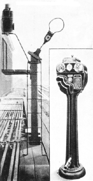
Single line working methods. This illustration shows a single line token fitted to a lineside post to facilitate picking up and setting down. The inset shows the electrically controlled token holding instrument. With this instrument a second train token cannot be removed in error, either from that end of the section or from a similar instrument at the other end, until the first token is replaced in either instrument.
Other safety devices included facing point locks in which a bolt positively locked the point blades fully home in their normal and reverse positions so that there was no danger of a point blade standing away from a rail and causing a derailment. The point lock bolt was connected to a steel bar longer than the space between any two pairs of wheels on locomotives and coaches laid against the inside edge of the rail approaching and through the points. Before the points could be moved they had to be unbolted by a point lock lever in the signalbox, during which operation the bar, called the fouling bar, rose up to rail level. If a train was standing or passing over the fouling bar the wheel flanges prevented the bar from being lifted and in turn the points from being unlocked and moved.
On single lines it was thought necessary to have something more than the block system to prevent head-
From it was developed the staff and ticket system in which if several trains had to follow each other in the same direction over the single line the drivers of all but the last train were shown the staff but given a written ticket to proceed, while the last train of the group carried the staff. The tickets were kept in locked boxes opened by a key on the staff. Even this system was cumbersome; its place was taken on many single lines by the electric staff instrument or its similar but smaller related systems -
With the virtual standardisation of the two-
By 1900 the wonders and use of electricity were becoming known. The early years of the present century saw the introduction of track circuits, in which a weak electric current was passed through an insulated section of the running rails and when short-
Electricity was also used to power electric motors connected to points or signals which could be controlled a greater distance away from a signalbox than by mechanical means. Indeed there was (and is) an absolute limit of 350 yards on the mechanical operation of points by rodding from a signalbox and the practical limit for a wire-
The earliest application of automatic signalling in Great Britain was on the Liverpool Overhead Railway in 1893 where electrically worked semaphore signals were placed to danger by an arm on the back of a passing train striking a lever on a contact box fixed on the lineside. As the train progressed the operation of the striker arms altered the electrical connections to place the signals immediately protecting the train to danger and cleared the signals at the previous station to allow another train to proceed.
During the next 20 years, which saw the construction of most of the deep-

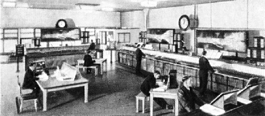
A modern all-
Main-
The track circuit was also gradually adopted to provide better protection in mechanically signalled areas controlled by normal block working, for it could be used to prevent a signalman clearing a signal leading to a section of line already occupied by a train.
Other allied safety devices similar in effect, if not in principle, were also used, including the lock and block system. This pre-
In the years before and after the First World War more changes became apparent in signals, particularly distant signals. One or two railways had begun to install three-
Indeed, because of the possible confusion between the two types of signal, the growing introduction of colour-
The Great Central Railway was the first to adopt automatic colour-
The 1920s and 1930s saw the gradual extension of colour-
During the 1930s the LNER introduced the first all-
You can read more on “Automatic Safety”, “The Magic of Modern Signals” and “Ruling the Traffic Routes” on this website.