
© Railway Wonders of the World 2025 | Contents | Site Map | Contact Us | Cookie Policy


Locomotive Valve Gears (1)
The Control of Steam in a Railway Engine
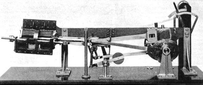
STEPHENSON VALVE GEAR, the joint invention of Williams and Howe in 1842, was first applied to locomotives by Robert Stephenson & Co, and is still in use throughout the world. This picture shows a working demonstration model of the gear in the Science Museum, South Kensington.
This chapter covers: Early valve gears, Carmichael’s valve gear, Gab valve gear, Stephenson’s valve gear, Allan’s valve gear and Gooch’s valve gear.
A RAILWAY traveller about to start a long journey often strolls up to take a look at the engine, and if he is non-
With the exception of a few isolated designs which the railwaymen term “freaks”, the driving wheels of every steam passenger and goods engine are turned by crankpins in the wheels themselves, or by a cranked axle, which in turn is operated by one end of a connecting rod, the other end being attached to a piston-
To enable the ports to be opened and closed at the right time for the steam to enter either end of the cylinder, push the piston to the other end, and then escape into the air through passageways and blast-

HOW THE LOCOMOTIVE WORKS. The above diagram illustrates in the simplest form how steam turns the wheels of a locomotive. The steam entering the inlet has pushed the piston from the front (right-
Cylinders, pistons, piston-
The very earliest valves were operated by a simple tappet gear. Two “fingers” were attached to the valve spindle, and another to the piston-
Early locomotives, including the famous “Rocket”, had a single eccentric for each valve, but it was not a fixture on the axle; otherwise the engine could not have been reversed. At first sight, a non-
To move the engine ahead, steam must be admitted in front of the piston; to move it backwards, steam must enter the cylinder behind it; and to enable the valve to “keep its relationship”, as one might say, with the piston at every part of the stroke, a different setting is necessary for either direction of movement of the engine.
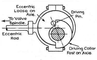
AN EARLY VALVE GEAR, in which a loose eccentric on the axle is driven by a collar and driving pin. The “Rocket’s” gear worked on this principle.
On the “Rocket” and its contemporaries, this was accomplished by leaving the eccentric loose on the axle, and driving it by means of stops, one set for either way. The “Planet” type of engine, which succeeded the “Rocket”, had inside cylinders, and the eccentrics were set close together in the middle of the driving axle, between the cranks. This enabled them to be combined on a sleeve, which was loose on the axle. A plate with a hole in it was fixed to the outside of each eccentric, and a collar on the axle outside of this carried a peg which fitted the hole.
One collar was set to drive the eccentrics for forward, and the other for backward motion, the sleeve carrying the eccentrics being capable of sideways movement, sufficient to allow either pin to engage, by a treadle on the footplate. The “ahead” and “astern” positions of the eccentrics were, of course, exactly opposite, and so the treadle could not be operated unless they were moved half a turn, or the engine moved to suit. The eccentric rods were not therefore directly connected to the valve spindles, but drove them by a hook and pin, which could be lifted out of engagement by a handle on the footplate. To reverse the engine the driver had to move the treadle half-
Valves at that time had no lap; that is, they just spanned the steam ports and no more; the eccentric was therefore placed at right angles to the main crank. If the eccentric were 90 deg. ahead of the crank, the engine ran forward; if 90 deg. behind it, the engine went backward. A Dundee engineer named Carmichael devised an arrangement requiring only one fixed eccentric. He connected the valve spindle to one end of a centrally-
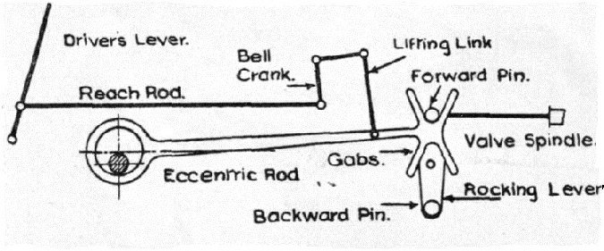
CARMICHAEL’S VALVE GEAR made use of a single eccentric and a pair of V-
By this time locomotive engineers had found that it was wasteful and unnecessary to admit steam during the full piston stroke; they thereupon lengthened the valves by adding a lap at either end, so that the port was closed before the piston had made its full travel. The opening time, however, still had to be the same -
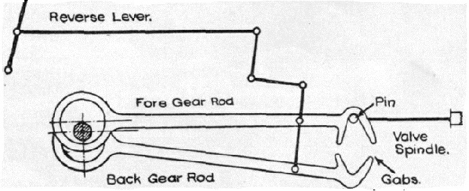
IMPROVED GAB GEAR, with two eccentrics, so arranged that lap and lead could be given to the valve to enable the steam in the cylinder to be used expansively. In the above diagram the gab of the forward eccentric is engaged with a pin on the valve spindle. On moving the reverse lever the forward gab is disengaged and the back gear rod comes into operation.
The next step was to provide an eccentric for each direction of movement, and fix a single gab on the end of either rod, connecting up by suitable rods to a lever on the footplate, so that the driver could engage either gab at will, with a pin in the valve spindle. There were several variations of the gab motion. Some had the gabs pointing downwards towards the valve spindle; some had them pointing upwards; and some had one above and one below, so that they faced one another, and one engaged directly the other disconnected. The final arrangement was a double gab on the valve spindle itself, the ends of the two eccentric rods being connected by a bar.
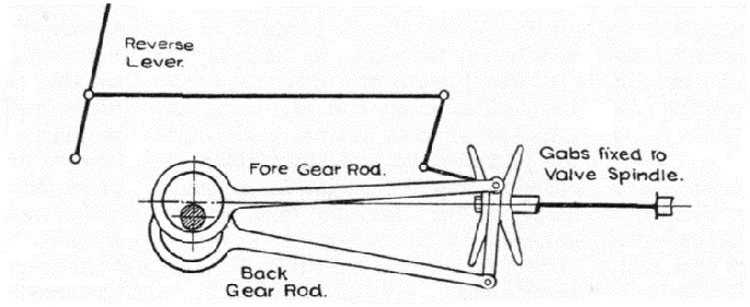
DOUBLE GABS on the valve spindle were used in the final development of the gab gear, and the two eccentric rods were connected by a bar as shown in this diagram. This gear did not permit of variation in the point at which steam was cut off from the cylinder.
While all these arrangements worked well as reversers pure and simple, the fixed cut-
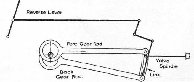
FULL FORWARD. This diagram shows the Stephenson link motion reversing gear, with the reverse lever set for running forward. In this position, the maximum movement is transmitted to the valve spindle.
There are various forms of the Stephenson link motion itself, but all of them have the two eccentrics, one set for forward and one for backward gear, the ends being coupled to a curved slotted link. Links themselves are of several kinds. There is the regular “open” locomotive link, which has an open slot, and the fork-
Then there is the “launch” link; this also has the open slot, but the eccentric rods are coupled to lugs on the concave side of the link, opposite the ends of the slot. The “box” link has no open slot, but a curved groove machined out on one side of it, in which the die block works; the eccentric rods, which are not forked, work on pins fixed in the plain side. One advantage of this type is that the pins line up with the die blocks in full forward or backward gear, so that the movement of the valve rod follows the movement of the eccentric rod exactly; just the same, in fact, as though they were directly connected. This minimizes “lost motion” due to any wear or slackness in the parts, and also gives better valve movements when the engine is running notched up, as there are no “offset” connexions for which allowance would have to be made.
Connexion between die block and valve spindle is made in a variety of ways. Where the cylinders are inside the frames, with valves between, or with outside cylinders having valves inside the frame, direct connexion is possible. A casting known as a motion plate, or spectacle plate, is bolted across the frames a little way behind the cylinders. This carries two large bearing bushes, in which work extensions of the valve spindles. On the back ends of these are fitted large forked ends, each carrying a pin, on which the die block is mounted. The links work between the jaws of the forks. In other instances, the valve spindle extensions do not work in guides at all, but are suspended from swinging levers pivoted to the frames.
This is really the better plan, as it compensates for any slight misalignment of valve spindle and extension, and prevents undue friction in the motion and excessive wear on the glands.
This direct connexion is also used for inside cylinder valves, when the steam chest is above or below the cylinders but inclined towards the centre of the driving axle, instead of being parallel to the cylinder bores. A typical example of this was to be found in the old Stroudley “Gladstones” of the London, Brighton and South Coast Railway, where the piston rods passed over the leading coupled axle, and the valve spindles below it, the former inclining downward and the latter upward, the centre lines meeting at the middle of the crank axle. If, however, the valve spindles and piston rods are parallel, this is not possible, as the drive would then become what the railwaymen call “skew-
Yet another arrangement is needed when the cylinders are outside and the valves on top of them. A short shaft with two pendulum levers is carried in a substantial bearing on top of the frame; the outside lever is connected to the valve spindle by a short link. The die block works on a swinging arm pivoted to the inside of the frame, and movement is transmitted from this to the inner pendulum lever by an inclined coupling-
The action of the gear is simplicity itself. Each eccentric is set so that when the crank is on dead centre the valve just begins to open the steam port, with the motion in “full gear”; that is, with the eccentric rod lining up as near as possible with the valve-
The locomotive invariably starts with the gear in this position. As soon as it gets under way the driver “notches up” by bringing the reverse lever a little towards the middle. This lifts the link; and the die block, instead of being right at the end of the slot, is now a little way from it. It is obvious that there is less to-
Some engines will run in either direction, with the lever in the middle, and die blocks in the middle of the link; the advance of the eccentrics, due to the valve lap, is responsible for this apparent paradox. As stated earlier, the eccentrics do not come exactly opposite, each one being advanced beyond the “right angle”, to compensate for the lap and lead of the valve; and as this advance is in the direction of motion the angles will be on the same side of the crank. Therefore, a line drawn through the centres of the eccentrics will not pass through the centre line of the crank axle, but a little to one side of it. As the two eccentrics are, of course, firmly fixed to the axle, it naturally follows that as the eccentrics revolve, this eccentric centre will sometimes be in front of and sometimes behind the true centre of the axle. The net result is that the whole link swings bodily back and forth, in addition to the movement at the ends given by the “wobbling” of the eccentrics themselves. When the die block is in the middle of the link it escapes the “wobble”, but is moved by the bodily swing of the link; and, this being just sufficient to move the valve and open the port at either end, steam enters the cylinders and the engine keeps going. Many of the Brighton tank engines designed by Stroudley would run at quite a good speed, in either direction, in mid-
All motorists know the advantage of advancing the ignition as far as possible when a car is running at high speed. A Stephenson link motion locomotive, running at high speed with the gear notched well up and the die blocks almost in the centre of the links, presents a striking parallel. The ordinary type of motion, in which the fore-
The steam ports are opened a little sooner than they are when in full gear. Everything in this world takes time; and it requires a certain amount of time for the steam to pass through the port and exert its full pressure on the piston head. When the engine is moving slowly, the port need not open so soon; but when it is running quickly it is obvious that an early opening of the steam ports will help to ensure full pressure on the pistons at the beginning of the stroke, not only maintaining the speed, but also enabling an early cut-
Despite its advantages, the Stephenson link motion has fallen from favour during recent years; this, however, is not due to any inherent disadvantages in the gear itself, but rather to mechanical drawbacks which make it unsuitable for very large engines.
The driving axle of a modern express passenger or heavy freight engine is massive, to say the least; and eccentrics suitable for fitting on these axles, and carrying straps of sufficient size to drive a valve gear of corresponding dimensions, become unwieldy and present a new problem in the matter of adequate lubrication and the avoidance of excessive friction. A big eccentric running hot and beginning to bind forms a very effective band-
Valve gears dispensing with eccentrics are now therefore used on all modern locomotives where the eccentrics, if used, would be “outsize”. For the smaller types of locomotives, however, the gear continues to hold its own. It is, for example, extensively used on the Great Western for two-
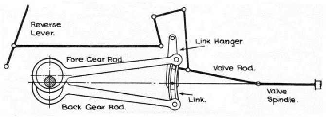
GOOCH’S GEAR. This reversing motion, designed by Daniel Gooch in 1847, had curved links supported by a hanger. The valve rod terminated in a die-
The idea and principles of the Stephenson link motion have been applied to other forms of valve gear. Daniel Gooch, the first locomotive superintendent of the Great Western, devised a link motion in which the link itself was not raised or lowered for reversing, but swung from stationary hangers in what would be mid-
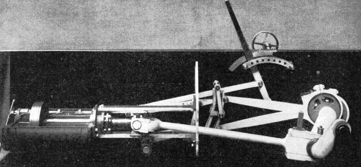
IN FORWARD GEAR. The Gooch valve motion set for running ahead. This fine model in the Science Museum, South Kensington, can be operated by the public and clearly shows the application and working principles of the Gooch gear.
Another variation derived from the Stephenson gear was the Allan straight link motion. Alexander Allan, of Crewe works, combined the ideas of the Stephenson and Gooch gears and used them with a straight link, which he claimed was easier to machine up than a curved one. The weighbar or reverse shaft had two arms for each set of gear; one arm had a “drop” or lifting-
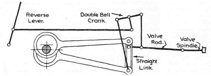
THE STRAIGHT LINK of Allan’s valve gear, here shown set for forward running, is moved upwards to reverse the direction of travel, and at the same time the valve-

ALLAN’S STRAIGHT LINK MOTION, designed in 1855, made use of two eccentrics for forward and reverse gear. The reversing lever shifts the link, which is straight and not curved as in the Stephenson and Gooch gears, and at the same time moves the die block attached to the valve rod seen at the right of the picture.
You can read more on “Locomotive Valve Gears -
“The Shay Geared Locomotive” on this website.