
© Railway Wonders of the World 2012-

Railways Under London
Driving Iron Tubes Far Below the Streets of the Metropolis

SURVEYING THE ROUTE. The preliminary survey of a tube railway is carried out above ground, and the ends of the surface lines are marked by metal plugs in the pavement. From these main survey lines, the centre-
JUST over three hundred years ago, in the reign of the unfortunate Charles I, London saw the introduction of the first means of public transport. But the court gallants with their ladies, daintily stepping across muddy gutters into hackney coaches, never dreamed that one day under the very ground over which these early vehicles ran, men would be carried along in iron tubes through the earth’s darkness. To-
Tubes were the outcome of the development of railway tunnelling. Marc Isambard Brunel, the famous railway engineer, while working for the British Government in the Chatham Dockyard, devoted a close study to the shipworm. He visualized that the methods of the shipworm -
Later, when Peter William Barlow was building Lambeth Bridge, in 1862, and sinking cast-
Barlow’s pupil and assistant. James Henry Greathead, built the Tower subway in 1869. This was the first “tube”. Greathead subsequently revived the project of the City and Southwark subway. This line was constructed as the City and South London Railway. After this venture Greathead became associated with other schemes for tube railways in London.
Greathead’s shield was originally driven forward by means of screw-

TRANSFERRING THE CENTRE LINE, below ground. The man in the service shaft behind the hoarding is adjusting one of the two shaft wires so that they line up with a point over which the engineer's theodolite is set in the street.
ROTARY EXCAVATORS are used to bore the great underground tunnels of the Tube railways. The revolving spokes, with cutters attached, are worked by powerful electric motors, and the excavators are driven forward by hydraulic rams.
The main principle of the construction of tube railways -
Construction proceeds from several points along the line of the route allocated, and on completion the various sections of the tunnel or tube link up in perfect alignment. Since his work is below the surface, and since he has to contend with unforeseen geological difficulties, the tube engineer has none of the advantages of ordinary visual checking on his operations.
The maximum deviation from the true line permissible in a half-
This accuracy may be emphasized by the fact that the shields for adjoining sections of the tunnel are erected in the earth in some instances nearly a mile apart and driven forward to meet one another. Their respective positions and the directions of the drive have to be ascertained solely from lines and markings, in the vertical supply shafts, in the headings, and in the sections of tunnel already constructed. No bore-
The latest example of tube railways in London is on the line between Finsbury Park and Cockfosters, completed in 1933. The method of working embodied in the construction of the earlier Morden extension, completed in 1926, can be considered typical and offers an excellent illustration, as the line had to be built through difficult strata, and compressed air had to be employed.
The extension was from Clapham to Morden, a distance of five miles. Apart from the last half mile, the line is of the usual type of tube design, with running tunnels of 11 ft 8¼ in diameter and situated on the average 40 ft below the surface. At the stations the tunnels widen to 21 ft 2½-
The first task on the extension, as on all railway enterprises, was the surveying of the route. On large-
Where there are curves on the tube railways the tunnels have to widen, but apart from a short stretch near Clapham South, the curves on the extension were so easy that the 11 ft 8¼ in standard was adhered to. The centre lines of the tunnels were estimated from arbitrary lines set out along the streets.
The survey taken, and the route of the extension finally determined, details of construction were arranged. The tunnelling work was divided into eight sections. Between Tooting Broadway and Colliers Wood the tunnels were divided in order to facilitate operations between the former station and Trevelyan Road, where the ground was water-

FAR BELOW GROUND, the centre line of the tunnel is transferred from the surface survey, made in the street above. The engineer adjusts his theodolite in line with two plumb-
Before construction could begin shafts were sunk at the eighteen places from which tunnels were to be driven. These shafts served to convey materials and supplies down to the builders and to hoist up the spoil; they also permitted the survey lines points on the surface to be transferred below ground
On the Morden extension the shafts were relatively small, being merely 10 ft 6 in diameter in comparison with the 30 ft of those on the older tubes. The reason for this was that, while the shafts on the older tubes were retained and had lifts installed in them, on the extension the shafts were only temporary. as the station platforms were to be reached by means of escalators.
The method used for finding the position and direction of boring below the surface was quite simple. When a shaft had been sunk to the required depth, a temporary tunnel was driven from it out to the proposed site of the main tunnel itself. A theodolite was next erected on the surface, on the centre-
A second wire, hung from an adjusting screw, was then suspended from the near side of the shaft, the two wires being as far apart as the shaft would allow The second wire was adjusted across the field of view until it coincided with the first wire. The two wires then lay on a true line at right-
The next step was to transfer the centre-
Once the base-
When the engineers were confronted by a clay strata, a space the size of one ring was built by hand and timber piles placed between the clay and the shield. As the shield advanced it forced the timber into the clay, breaking it up so that it could be shovelled back by the miners. Hydraulic rams round the side thrust forward the shield. These rams press against the iron lining of the rings and by modifying their thrust the shield can be negotiated or steered to bore the desired course. For boring curves, therefore, the pressure of the rams has to be increased on one side and lessened on the other. The manipulation of the rams requires considerable care.

A GREATHEAD SHIELD at work in the construction of a tunnel. Miners in the chamber within the shield break down the earth in front of them and other men shovel the spoil to the rear. Around the rim of the shield are hydraulic rams which force it forward. The control gear for these rams is at the left of the miners’ rectangular chamber.
When boring twin tunnels for tubes it is the practice not to begin the second until the other has advanced some distance, so that two shields never operate side by side. A “chamber” or space is cut in front of the shield before each drive. Without this preliminary excavation the shield would only be forced into a solid face, and there would be nowhere into which the broken earth could collapse.
After the shield has completed a drive, it is all dismantled except its round steel-
Two types of shield employed are the Greathead and the rotary excavator. Men work inside the Greathead shield, shovelling out the earth as it is broken down by the shield. The rotary excavator throws back the spoil mechanically by means of revolving cutters, but it is used only for driving through clay.
Test bores are usually run through the ground which has to be tunnelled. These tests give an approximate indication of the strata to be encountered; they cannot reveal all details. On the Morden tube extension test bores were made not only from the surface but also ahead of the shields. They were made with a carpenter’s long-
Compressed air has to be used when subterranean excavations are being carried through waterlogged ground, such as that near Merton during the Morden extension. The tunnel is converted into an airtight compartment, and the air pressure raised sufficiently to keep back the water. The pressure varies, according to requirements, from 5 lb per inch to 35 lb, but the average is roughly 10 lb. If the tunnel is being constructed beneath a river, the pressure is altered with the ebb and flow of the tide, which cause variations in the force of the water threatening the workings. The air compressing plant is similar in design to the machinery working the pneumatic drills used in highway reconstruction.
A compartment, termed the air-

A SERVICE SHAFT. Before tunnelling can begin a large vertical shaft must be sunk to enable material and supplies to be taken to the working point below the surface. The service shafts on the Morden extension were 10 ft 6 in in diameter, but those used in the construction of London’s earlier tube railways were as much as 30 ft in diameter.
While the shield is being driven steadily forward by the rams, the course has to be constantly checked and measured off to agree with the engineer's plans and prints. This procedure is called banding, as all measurements are made with a steel tape or band which is proof against either stretching or shrinking. The position and direction of the tunnelling is checked by iron dogs or hangers fixed to the roof, set some 35 ft apart, to which plumb-
The man at the shield adjusts this slit until it coincides with the plumb-
When the engineer desires to check the level of the shield he has hangers bolted to the roof of the tunnel on which a movable pin is set to be on a precise level parallel with the gradient. From these movable pins, boning rods shaped like the inverted T are suspended. The true axis level of the tunnel is shown by the crossheads of the rods.
Determining Direction
The workman in the shield once more holds up his piece of wood to the fiddle, but this time with the slot horizontal. Then, taking a sight along the top of the crossheads, he signals for the piece of wood to be raised or lowered until the illuminated slit coincides with his line of sight. The position of the top of the fiddle is then noted in relation to the slit. If below the slit, the shield is low; if above, the shield is high; and, as before, such adjustment as may be needed is carried out by the rams.
Square lines set out at right angles to the centre-
These precautions are taken when the shield is tunnelling on the straight. On curves the engineer provides the ganger with a number of figures which show that for every foot in advance of the front plumb-

DRIVING THROUGH THE EARTH. To the right is an electrically-
In this manner the Greathead shield, or the rotary excavator, is guided as it bores its way through the solid earth; and in this manner London’s network of tube railways has steadily increased and is increasing. The latest devices of modern science are pressed into service to assist the engineers, but their task will always be associated with difficulties and dangers.
Before the construction of any railway can begin, the engineers have to be quite certain that the proposed route offers complete safety to the passengers. The gradients, the curves, the track bed -
The most important part of this system is the operation of signals. These signals not only serve to govern the movement of trains, but they also limit the traffic working, and thus determine the number of trains that may be run in safety.
Nearly all signals and points are operated either by compressed air or electricity. The breaking of any wire or the failure of the power supply causes a signal to indicate “Danger”, whether the track is clear or not.
One of the most vital safety devices on the underground is the track circuit system. By means of the track circuit the signal immediately behind a train is automatically set at danger.
The working of the track circuit is simple. The running rails are divided into lengths of track electrically insulated from one another. Current passes along the rails on one side of this section, through an instrument called a track relay, and back through the rails on the other side of the section.
How the Signals Work
When current flows through the track relay its contacts are closed, completing a circuit for the signal controls. When a train enters the section, the current, instead of passing through the track relay, travels by a shorter path through the wheels and axles of the train. This breaks the signal circuit; the signal indicates danger, and remains at danger until the train has passed out of the section controlling that particular signal. These automatic signals are usually installed on straight stretches of track where there are no points or junctions.
Where points have to be worked, signal cabins are provided. A remarkable feature of these cabins is an illuminated diagram showing in miniature the part of the track controlled from the cabin. On the diagram the track is divided into lengths that represent various track circuits. If the line is empty, the diagram is illuminated by electric lamps. As soon as a train enters a section the lamps are extinguished and the dark spot on the diagram indicates its presence. This diagram enables the signalman to know the exact position of any train on his particular section, and it is possible for him to direct it without seeing or hearing it.
The power-

WORK UNDER COMPRESSED AIR has to be introduced when tunnelling is carried out in water-
So that the signalman shall not pull a lever that would set a wrong route, these levers are specially interlocked, and even if an incorrect lever were pulled to give the “Clear” signal while the section of track was engaged, the track circuit would independently keep the signal registering “danger”.
In this straightforward yet efficient manner -
 Many of the most modern point-
ABSOLUTE ACCURACY is essential when tunnelling from different points, to meet underground. This necessitates constant checking of the Greathead shield's position by means of plumb-
When the signalman is changing the points, he can pull his lever only halfway until the points have moved and have been safely re-
Where electrical interlocking is used, small illuminated dials can be seen above the levers. A red light shining over these levers means that the corresponding signals are at “danger”, while the point lever, if in the unoperated position, has a bright “N” gleaming above, thus indicating that the points are in the “normal” position, and both mechanically and electrically locked. As soon as the signalman pulls a lever a letter “R” shines out, and tells him that the points are in the “reverse” position.
Underground railways have yet another remarkable safety device. The most perfect signalling and point-
The efficiency of this tripcock is tested by each train. Whenever a train approaches the apparatus, a lamp is switched on automatically. As the train goes by, the tripcock, if in correct working order, presses down a spring and extinguishes the light. If the lamp remains lit it acts as a warning, for it means that the tripcock is faulty and could not engage with the arm on the train were the signal at danger. The driver must report the defect at once, and it is repaired forthwith.
Guarding Against Illness
Underground and tube trains are fitted with a device known as the Dead Man’s Handle, which prevents the train from running without control should the driver be taken ill. This handle comprises a flat knob on the controller handle with a spring easily depressed by the driver’s hand when operating the control. While the knob is kept down, the control functions in a normal way, but should pressure be released by the driver, the brakes are applied automatically.
As a further precautionary measure, the control governor prevents the driver from moving his train out of the station unless the Westinghouse brake is in good order and the tripcock device at the front end correctly set. The brake check is worked by an electro-
Since all these devices are in their turn controlled or operated by other devices, the underground railways have to be prepared for any breakdown in these controlling systems. Should this occur, it might be necessary for the driver of a train to cut off the power in his section of the track. This can be easily accomplished by bringing together the two bare wires which are suspended throughout all the tunnels of the tube railway. The instant the wires are contacted, circuit-
If the current is cut off, trains are not plunged into sudden darkness, because both the trains and the tunnels are provided with emergency lights. To assist the task of the traffic manager's department, and to give the engineering staff necessary information, a check and a complete record is made of times taken by the trains to do their journeys and of the intervals between succeeding trains. This record is registered by means of a headway chart. This chart is a circular strip of paper marked up into divisions representing the twenty-
Besides the record clocks, machines have been devised which register not only the place of delay, but also the cause of the delay and the manner in which it was corrected. Several stations possess illuminated signs, termed “running indicators”, which inform a driver whether he is in front of or behind his scheduled time, and how many minutes have to be allowed or regained.
The precision with which the official schedules have to be observed will be appreciated by the fact that nearly 1,500 trains a day are controlled by the Camden Town signal cabin, and over 1,600 a day by the Kennington signal cabin. The total number of lever operations per year in these two signal cabins exceeds 7,000,000.

EMERGENCY MEASURES. If necessary the driver of a tube train can cut off the supply of electric current on any section of the line by pinching together two bare wires which run the length of the tunnel. The driver can then speak to the power sub-
Apart from these safeguards connected directly with the operation and running of trains, there are other safety devices embodied in the construction of the Underground stations themselves. All passenger lifts, for instance, are mechanically controlled as a check on the lift operator. A safety catch ensures that a lift can neither descend nor ascend unless both the doors and the folding gates have been closed. This catch is a switch placed in the path of the door or gate and is kept open by a spring, so that no current can pass to the lift, which then cannot move. The lift can start only when the closed doors and gates have overcome the resistance of the switch's spring.
The speed of the lift is regulated by a lift governor, which consists of two metal balls attached to a vertical shaft. The balls are free to revolve and move in a vertical position by centrifugal force. Should the lift exceed its speed-
In the most unlikely event of a lift cable breaking there is a device which would open a contact switch, thus shutting off the power from the motor and instantly stopping the lift.

THE DRIVER of a tube train is safe-
DEAD MAN’S HANDLE is a safety device which ensures that the train is always under proper control. Should the driver let go of his control handle through illness or nay other cause the spring “takes charge”, and instantly puts on all the brakes, thereby stopping the train until the handle is properly operated again.
To enable lifts to be worked automatically, and to govern acceleration and deceleration, all lifts are fitted with “landing control” gear. This gives the lift attendant sufficient time to collect tickets and to supervise passengers entering and leaving lifts, to close gates and to prevent overcrowding. Every shaft to a tube station contains cither two, three or more lifts, and if for any reason one of these should stop, another can be quickly lowered or raised until level with it. Then passengers may step out of an emergency door into the second lift and continue their journey. Few people notice these emergency doors in the tube lifts because they are usually hidden by a display of framed advertisements.
The cables supporting the lifts are manufactured and tested to haul nine times the weight of a lift loaded to its maximum capacity. At each landing stage the operator can see at a glance the exact position of the lift, an indicator telling him whether it is stationary, ascending or descending.
In the more recently built stations escalators have replaced lifts. These escalators have their own particular safety appliances. Occupying a conspicuous position at the top and the bottom of the moving stairway, small metal drums have been installed. Each drum has a paper diaphragm concealing a plunger. It, in the event of emergency, it is necessary to stop the escalator, the diaphragm can be easily broken through and the plunger pressed. This at once cuts off current from the escalator.
Should the chain of an escalator break or should the escalator move too rapidly, a contact switch opens and stops the escalator by cutting off its power.
Escalators are also provided with brakes to prevent a running back should the electricity suddenly fail.
These mishaps seldom occur, but the London Passenger Transport Board, like its predecessors, leaves nothing to chance.
At some stations a gap wider than normal occurs between the train and the platform edge. To warn passengers of this, lights shine out from below the platform's coping. To make the warning more emphatic, these lights are often switched on automatically just before the train stops. This is effected by having a special projector lamp below the coping, which shines on to a photo-
On the train coaches the doors are worked by air pressure and are electrically controlled. They close slowly, and the air pressure diminishes immediately before they are shut and enables them to be kept open easily by hand. The edges are fitted with soft rubber, so that there is no danger of anyone crushing his fingers. Not until all the doors are closed does the guard receive a light signal, and neither can the bell in the driver's cabin signal him to start.
There are other less prominent but scarcely less important provisions made for the passenger’s safety. The ticket offices and corridors are paved with non-
The tunnels are constructed of cast-
No other system in the world is more efficiently protected against possible mishap, and the tube and underground railways have justly earned their reputation for being the safest method of transport in existence.
Overhaul and Maintenance
After the adequate provision of safety devices on the tube railways, the most important consideration is the overhaul and maintenance of the rolling-
The overhaul programmes are arranged in advance, and the amount of material required is assembled in the shops before the cars arrive. The number of cars that have to go to the works for an overhaul every year is nearly 1,500. This figure includes both the motors and the trailers.
The works are planned on a progressive system. Vehicles travel from shop to shop on conveyers, and stop at various points to allow for inspection and repair.
These conveyers are rails laid across rollers which bridge haulage chains and are used to support the vehicles. The speeds of these conveyers arc regulated to synchronize wherever necessary. The shop is planned to deal with forty cars a week, although the system is adjustable, and the speeds of the conveyers can be altered. The power required to drive these 185 ft. long conveyers is 2.5 horse-
At various intervals there are push buttons so that in the event of an accident or obstruction the conveyer can be stopped. Near each push button is a red light, which indicates whether the system is working or not. From these lights a foreman can see at once if all the conveyers are working satisfactorily. Should the conveyers or haulage chains propel cars beyond the correct limits, a trip lever, operated by the truck wheel, automatically cuts off the current.
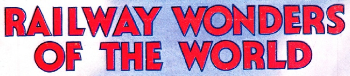
HOW THE CARS ARE CLEANED. This is the “blowing-
The overhaul work is divided into five chief sections -
Wherever practicable machinery and tools are brought to the work on hand, not the work to the machines. Each section of the work is a machine-
When cars are sent to Acton for overhaul, they enter the works in the lifting shop. The complete body is then taken from its running wheels and put on to the accommodation or workshop bogies, which are waiting on a nearby track. The haulage chains already mentioned, are fixed to the service bogies and carry the load on to the truck shop. When the trucks of the car bodies have been inspected and, wherever necessary, repaired, they are dispatched to the truck storage building until wanted for reassembling.
After the car body has been put on the accommodation bogies, all the seat cushions and seat backs are removed, taken to the seat-
Meanwhile, the car bodies themselves are being cleaned in a “blowing-
Final Tests
After cleaning, the car-
The car is then taken along farther by another haulage chain, and eventually transferred on to a car-
When the car has been finished with on the assembly conveyer, it is taken, by means of haulage, to the paint shop.
When repainting has been carried out, the car body returns to the lifting shop. Here it is raised again and put back on to service bogies. Twelve cars can be dealt with simultaneously, as there are four separate tracks each having three pits over which the bogies rest.
Before the crane -
The car is now ready for the running track again and is moved away to train sidings to await return to service.
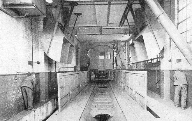
READY FOR SERVICE AGAIN. The reconditioned car, cleaned, painted and overhauled, is lowered on to its service bogies and connected up again, for the final inspection. If it passes the tests, and brakes and electrical circuits prove to be in order, it will be moved to the train assembly sidings, ready for active service once more.
You can read more on “Electric Traction”, “Power for London’s Transport” and “The Underground Electric” on this website.
You can read more about “London’s Underground Railways” in Wonders of World Engineering