
Seen From the Train
The meaning of familiar objects along the track

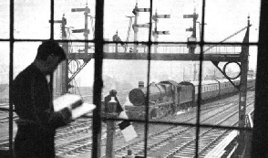
A SIGNAL GANTRY viewed from a signal-
THERE are many objects on the railway seen by a passenger in a train with the uses of which he may not be familiar. In this chapter the functions of certain of the commonest of these are explained.
At every quarter-
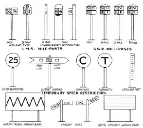
There is considerable variation in both the design and location of mile-
The Great Western type of post is similar, but it is ingeniously designed in such a way that the mile forms the upper part of the indication, the quarter, half, or three-
On the Western Division of the LMS the mile-
The mile-
On the Great Northern Section of the LNER, the down side of the line is favoured, and the posts run through from zero at King’s Cross to York. From here, over the North Eastern Area, there is one series from York to Newcastle, and another from Newcastle to Berwick, all on the down side. But a change is then made to the posts of the Scottish Area, which are measured from zero at Edinburgh (Waverley), and are all on the left side of the line leading from Waverley, which is, of course, the present up side between Berwick and Edinburgh.
The Great Western Railway favours the up side of the line, and the Western Section of the Southern Railway (the late London and South Western Railway) the down side. All the Great Western series follows the original routes; this leads to some curious mile-
The speed restriction signs, illustrated on this page, require some explanation. The one marked “25” indicates a permanent speed restriction to twenty miles an hour. Next come the movable signs used in connexion with track relaying and other permanent way work. First is the green board, fixed, similarly to a distant signal, half a mile away from the site of the speed restriction, and displaying white and green lights at night, side by side. Then comes the “C”, or “Commences” sign, where the speed restriction begins, followed by the “T”, or “Terminates” sign, at the point where normal speed may be resumed. All these signs are illuminated at night, and frequently the figure to which speed must be reduced is now also displayed at the outer “caution” sign.

MILE-
The “levelling post” shown at the right hand side of the series of diagrams is generally found as one of a series erected at the line-
At the bottom of the diagrams are seen, on the left, the type of warning board used on the Great Northern Section of the LNER to indicate to drivers the beginning of water-
Between these are seen two varieties of gradient posts, which indicate the changes of gradient. An upward tilt of the indicator shows, of course, the beginning or end of an up gradient, and a downward tilt a down gradient. On some lines the full “1 in 200”, or whatever the gradient may be, is inscribed; on others merely the significant figure “200”. On certain routes, such as the Great Eastern Section of the LNER, the infinity sign is used instead of the word “level”, where level track is indicated.
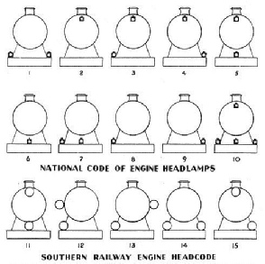
The second series of diagrams, on page 1551, explains the arrangement of the headlamps carried on the front of locomotives on most of the railways in Great Britain. Readers will probably have noticed that lamps are mounted in this way by day as well as by night. The object is for these lamps to indicate to signalmen and others concerned with the working of the traffic the exact nature of each train.
 THESE DIAGRAMS INDICATE: 1. Express passenger train; breakdown train going to clear line; or light engine going to assist disabled train. 2. Ordinary passenger train; or breakdown train not going to clear line. 3. Empty coaching stock train; express fish, meal, fruit, or other train carrying “perishable” traffic, or horse and cattle train, composed of coaching vehicles fitted with the continuous brake. 4. Fish, meat, or fruit train, or express cattle or express freight train composed of freight stock. Class “A” (speed, 30 miles an hour). 5. Express cattle or express freight train, Class “B” (speed, 20 miles an hour). 6. Light engine or engines; or engine with brake-
In the national headcode the positions used are four only. One is at the base of the engine chimney, either on the top of the smoke-
Of all the headlamp indications, probably the most familiar is the pair of white lights, one over either buffer, which indicates “Express Passenger Train”. Then there is one single light at the base of the chimney, indicating “Ordinary Stopping Passenger Train”. Other indications, for freight trains of various kinds, light engines, and empty coach trains, are explained on the diagrams. The only code requiring the use of all four lamp-
On the Southern Railway, however, the complexity of routes is such that the lamps are used to indicate the route that each train is to follow, rather than the description of the train. Further, in the daytime, for ready recognition, the lamps are replaced by circular sheet metal disks, painted white. Some of the best-
In addition to the four positions of the national headcode, there are lamp and disk positions on either side of the smoke-
On the Great Eastern Section of the LNER also, disks are used in the day-
In Scotland an ingenious type of route indicator is employed on the Caledonian and Glasgow and South Western Sections of the LMS. It consists of a frame with two movable arms, painted white, which can be altered in the manner of the hands of a clock. Most familiar of all its positions, probably, is with the two arms set horizontally, at “a quarter to three”, which indicates the main line from Glasgow to Carlisle via Carstairs. The engine of the “Royal Scot”, if working through from Glasgow to London, is often seen arriving at Euston with its Scottish indicator, at the base of the chimney, set in this position.
On page 1552 is a set of diagrams explaining the meanings of signals and ground disks, and certain of their variations which are most widely used. At the top left hand side appear home and distant signal-

THE INDICATIONS of various signals which are common over Great Britain are denoted in the diagrams. The use of the upper quadrant type is rapidly becoming more widespread, as it is of lighter construction and offers a greater guarantee of safety, for in the event of an accidental disconnection or break in the signal mechanism the arms drop to the horizontal or “danger” position.
The substitution is chiefly for purposes of economy. Provision must be made for the signal to return automatically to “danger” in the event of any breakage of its operating mechanism.
The lower quadrant arm had therefore to be provided with a heavy spectacle casting, holding the red or yellow and green glasses that move in front of the lamp, to provide a “balance” that would return the arm to danger should the rod from the base of the post break or become disconnected. But such a breakage, with an upper quadrant arm, would simply result in the arm falling to danger by its own weight, and a much lighter and more economical spectacle casting thus serves the purpose.
With both home and distant signals “on”, “danger” is indicated, and the train must stop. The home signal “off” and the distant signal “on” indicate that only one block section ahead is clear, and instructs a driver to “proceed with caution”. Both home and distant signals pulled off show that two or more sections ahead are clear, and permit the driver to “proceed at full speed”.
The upper, or home signal arms are square at the outer ends, and are painted red with white stripe on the side facing the driver; at night they display a red light for “danger”, and a green light for “clear”. The lower or “distant” signal arms are painted yellow, with a black stripe, and display at night an orange light when “on”, and a green light when “off”. Provision is made by locking, by means of a “slot” on the post itself, to ensure that the distant arm cannot be pulled off unless the home arm is also off, and to return the distant arm to danger when the home arm returns to danger, even though the balance weight of the former is still pulled off.
The corresponding indications with colour-
Reverting to the third set of diagrams, at the right-
In the centre of the diagrams the arm made in the shape of a cross is another variety of “draw ahead” signal; and the arm with two holes in is in use on the Great Western Railway to permit a train to “set back” -
“Ground Disk” Signals
Along the bottom of this diagram, at the left-
In the centre of the bottom row of diagrams are seen “ground disks”, which are fixed at ground level, and used to control shunting movements only. The low location is so that there shall be as little confusion as possible with the “running signals” controlling the through running. The new standard type of ground disk is on the left, in both the “on” position, when it displays a small white light, and in the “off”, when it shows green. The disk itself is painted white, with a red bar across. The older type, on the right, is a disk that rotates, showing a red face with a small white light when “on”, and a green side, with a green light, when “off”.
The last two diagrams, in the lower right-
Now if a train is brought to a stand for any appreciable time at a home or starting signal, Rule 55 of the Rules and Regulations requires the fireman to proceed to the signal box so that the presence of the train may not be overlooked. This is not necessary, however, if track circuit is in use, and if the line is track-
On the former Great Northern Railway, now part of the LNER, the “somersault” type of signal arm was used. This was pivoted in the centre instead of at the end. When the “somersault” signal was “"off”, it stood in a vertical position, away from the post.
This type of signal was introduced as a safety measure after an accident at Abbots Ripton, Hunts, in 1876. In that year the slot of a signal of the normal type had become blocked with snow during a blizzard and the signal did not return to the danger position when the lever was released.
Another unusual type is the three-
You can read more on
and
on this website.