
The Magic of Modern Signals (1)
New Electrical Devices Ensure Safety and Speed
THE MAGIC OF MODERN SIGNALS -
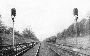
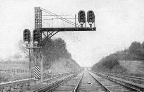
NEW AUTOMATIC SIGNALS govern the Southern Railway’s Main Up Line between Balcombe Tunnel and Three Bridges in Sussex. How they work is explained below.
THE first railway signals were used entirely as a protective measure. Safety was their sole purpose, and all that was required of a signal was to indicate cither “Danger -
This introduction of a time element is vitally important to-
New conditions demand new ideas and new apparatus, all of great importance to the traveller, though often unnoticed by him. The necessity for greater safety, the increase in numbers of trains to be handled, the operation of faster services, are vital things which call imperatively for corresponding improvements in the instructions given to the engine-
As the modern train pulls out on its closely-
The familiar semaphore arms, the coloured lights -
To govern speed as well as to indicate safety is the function of modern signalling. The simple semaphore signal, so well known to all travellers, has given place to a complicated system of grouped signals on all the busier lines. It is a system which mystifies the public, but which gives clear and definite instructions to the engine driver.
Instead of having only two positions -
In its horizontal position it indicates “Danger”; at an angle of forty-
Perhaps the most striking development is the use of colour-
Colour-
The advantage of such a multi-
The GREEN light would indicate “Proceed -
Such a signalling system, by increasing the information conveyed to the engine-
Alteration to the signal itself is only one of the problems of improved signalling. We have dealt, so far, only with the message conveyed to the driver of the train; an equally important consideration is the means by which the signal is linked to the cabin from which it is operated.
Power Signalling
Very long levers and rods were invariably used at one time These were operated by the signalman, and called for consider-
There are many important advantages derived from such a method, in addition to that of lightening the labours of the signalman It is possible, for example, to work signals placed at much greater distances from the signal-
These advantages apply with even greater force to the moving of points by the signalman, which is necessary whenever a train is to move from one set of metals to another. However close to the points the signal cabin is placed, the change-
Power signalling does away with this difficulty of exerting a considerable force at a distance, since the power unit can, if necessary, be located quite close to the points; and all that the signalman need do then is to control that power, instead of transmitting it over a distance.
Power signalling is thus a modern answer to the old problem of easing the work of the signalman, just as colour-
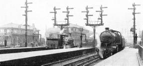
THE OLD AND THE NEW SYSTEMS. This view of Brighton station shows the semaphore-
There are. Indeed, it is in this field that the magic of modern signalling is fully shown; for although all improved methods tend directly towards greater safety, probably the most strikingly ingenious and effective inventions have centred round the prevention of accident.
The fundamental signalling safeguard, which was evolved in the early days and is still effective, is the block system, by which only one passenger train at a time runs on a given section of the line. If this safeguard can be definitely assured, collision is impossible.
It is in the methods taken to achieve this end that modern signalling has worked wonders. One of the first steps towards accident-
In other words, mechanical interlocking provides that control levers which should work in conjunction with each other are so constructed that they automatically check their own operation, and cannot, therefore, be made to work except in the predetermined and correct sequence.
Similarly, to prevent vehicles from moving inadvertently from a siding or yard on to a passenger line, safety points, which divert runaway wagons, came into operation in conjunction with the main line signals.
On this principle of the interdependence of one moving part on another a comprehensive safety system has come into being. By its means a continuous check is established, safeguarding every movement, and ensuring that certain necessary conditions must be fulfilled in their correct order before the corresponding indication is given.
The Interlocking System
To take a simple instance, suppose that a train on a main line has to leave this for a branch line at a certain part of its journey. As the engine approaches the junction the driver sees that the signal for the branch line is “clear”; and on an interlocked system he is then certain that the points must be correctly set for the change-
He knows that until the points are correctly in place it is literally impossible for the signalman to move the branch signal from “danger” to “clear”; so the driver proceeds with confidence because the apparatus itself automatically checks the change-
By ingenuity and skilful design, the signal-
One good example of the uses of electricity in signalling is the system of electrical repeaters; these check the indications given by signals that are out of sight of the signalman. Beside the lever which he operates is placed an indicator that is worked by an electrical circuit of which the distant signal arm is an essential part. If he moves the lever to the “Clear” position, the electrical indicator, or repeater, will immediately change to “Clear” also, provided that the signal arm has actually responded as desired. The repeater is worked through electrical contacts which are placed on the signal itself, so that the repeater is an instant and definite check on the out-
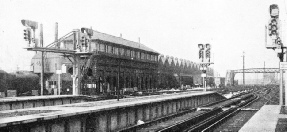
ADVANTAGES OF COLOUR-
Should the signal arm’s response be incomplete, or unsatisfactory, the repeater will at once call attention to this by indicating “wrong”, and thus it will warn the signalman of the failure.
A variation of this method is extensively used to make sure that an oil signal-
An effective method of checking the indications given by a colour-
Ingenious electrical devices are always watching to overcome the possibility of errors arising through accident or failure.
The immediate effect of such devices is to check the signalman’s work at every stage, protecting him from all avoidable errors, and relieving him of the physical effort necessitated by the operation of manual levers. Obviously the whole tendency is to promote safety, and a secondary advantage is that the traffic can be handled much more quickly and economically.
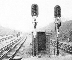
WORKED FROM A SIGNAL BOX 4 MILES AWAY. These remarkably interesting electric signals at Stanmore are worked from Wembley Park, 4 miles away, a distance that would have been prohibitive with a manually operated system. The Wembley Control Panel is illustrated below. One very striking feature of this installation is that the whole of the control of the signals and points shown by the diagram at the top of the panel is carried out over three live wires between Stanmore and Wembley Park. The casing near the line in the foreground houses a special stop mechanism which will automatically put on the brakes of any train attempting to pass the signal at “danger”.
All the foregoing developments in signalling are based on a system in which the control is in the hands of the signalman. But there is one method where a fundamental departure in practice is made, and the trains themselves actually operate the signals. This is known as automatic signalling, and the advantages claimed from its use are many and varied. They include the replacement of the human factor by tireless machinery; the lower running costs owing to the reduced wages bill; the greater speed of the automatic response, thus saving valuable time; and the economy effected by working the existing track to its maximum capacity.
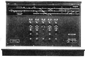
IT SHOWS TRAINS UPON THE TRACK. This Control Panel at Wembley Park operates the points and signals at Stanmore and shows by means of little lamps the movements of all trains between that station and Edgware. This installation was the first of its kind in Europe, and it has successfully demonstrated under practical working conditions how small thumb-
Automatic signalling is operated electrically, the rails themselves being used as conductors along which the necessary operating current flows. In a section of railway line which is automatically signalled the battery or other source of electrical power is at one end of the section, and the apparatus which it works is at the other end, the two sets of metals between acting as long leads to convey the current to and from the battery. It follows that where one rail in a section ends and the next begins a connecting joint becomes necessary, and this is the reason that one finds stout wires joining one rail to the next on railways employing such systems. It also follows that the insulation (electrical isolation) of one set of rails from another is of great importance.
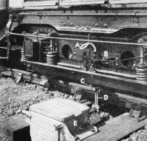
THE SIGNAL STOPS THE TRAIN. This device will automatically put on the brakes of a train attempting to pass a signal at “Danger”. On the power bogie of the train a pipe (A) is attached to the Air Brake, its inlet being opened by the trip lever (C), on coming into contact with the ground arm (D). The control box (E) moves the arm (D) in or out of reach of the trip lever in accordance with the signal indication. At (B) is shown a control wire for closing the air inlet to release the brake when the signal gives “all clear”.
If the pair of long lines comprising a section is regarded as a pair of long battery leads, it becomes easy to see how a train can be made to control a signal. The moment a train enters on a section, it joins the right-
By inter-
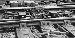
ELECTRICALLY OPERATED POINTS. The transfer of trains from one set of rails to another is now accomplished by points worked by electric motors, enclosed in steel boxes such as that shown at (F) in this picture. Two sets of points are worked from one machine through the lever (K). The correct positions of the switch tongues (G) are ensured by the detectors (I) which cause electric contacts to be made in the boxes (H) and (J), these working in conjunction with the signal lights. Thus the points must be correctly set before signal permission can be given for a train to proceed.
There is, however, yet another safeguard which can be embodied, and one that is almost human in its ingenuity. This is the automatic train control, which watches to see that the signal’s injunction is obeyed! And if a train enters a section when the signal is at “Stop” the automatic train control instantly and without fail does what the driver should have done -
The method employed is the familiar one of interlocked apparatus, the two sets of mechanism in question being the “danger” signal itself, and a special check apparatus, mounted inconspicuously beside the adjacent rails. On all the loco-
When the signal is not at Danger, the check apparatus on the ground remains inoperative, allowing trains to pass without interference. But when the signal is in the “Danger” position the moving arm of the apparatus moves to a position where it will touch a special projection on the locomotive, so putting on the brakes of any train attempting to pass it.
As soon as the signal permits, the mechanical “brakesman” returns to its original position and allows traffic to pass freely.
Modern methods have greatly lightened the work of the signalman, miniature levers or even little thumb-
The faster running must be controlled by more indications to the engine-
Thus, contrary to the general impression, every stretch of railway track presents its own problems to those responsible for the signalling there, and not only must the present conditions be met, but the contingencies of future development must also be borne in mind.
The signalman’s duties, which in the past were so largely manual, are now really those of a controller. Instead of the limited outlook of the past, he often has an electrical “map” of whole sections of the line in front of him, with indicators showing the position of the various trains at any moment. Instead of crude levers he has, in his charge, an extraordinarily efficient electromechanical system, flexible in operation, but rigidly interlocked for safety. And the contrast between the limited simplicity of the old style, and the almost unlimited capability of the new, forms a practical example of the amazing changes wrought by the growth of modern signalling.
ON THE ELECTRIFIED LINE TO BRIGHTON. Colour-
You can read more on
on this website.
