Climbing to the Summit of Mount Rokko San
RAILWAYS OF THE WORLD - 11

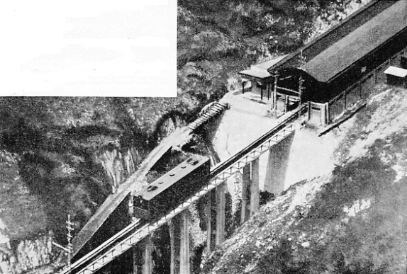
INTERMEDIATE STATION on the Mount Rokko San Cable Railway. This is the meeting-place of the ascending and descending cars on the lower and upper sections respectively. Here passengers have to break their journey and change cars.
MOUNT ROKKO SAN is a famous pleasure and health resort in Japan. It lies in the midst of a range of mountains between the great industrial cities of Kobe and Osaka. A commanding view is obtained over high peaks and picturesque valleys, while to the south the eye takes in the tortuous coast line. The wealthy merchants of Kobe and Osaka have built their summer residences on the plateau of Mount Rokko San, and have turned it into a vast garden, with all the art and refinement that has been handed down to them through the centuries.
Countless roads and paths wind their way through pine forests, leading in all directions, up mountains and down valleys. The whole district is a paradise for walkers, and Mount Rokko San is known throughout Japan as “the mountain of the five hundred roads”. One of the country’s best-known golf courses has been laid out here; well-equipped hotels, tennis-courts and playgrounds in beautiful surroundings, all sorts of amusements, and, above all, the invigorating climate have made Mount Rokko San famous throughout the country.
To meet the ever-increasing popularity of the resort it was decided to provide convenient means of communication between the two great cities and the top of Mount Rokko San. After the various possible alternatives had been investigated, it was decided to construct a cable railway up the slopes of the mountain. An aerial ropeway would not have been practicable in this instance because of the large number of passengers to be transported.
The cable railway of Mount Rokko San is one of the longest in existence; it has a route length of 1,939 yards, or 1 mile 179 yards. It connects Dobashi, a station on the Kobe-Osaka railway line, with the top of the mountain. The difference in level between the lower and the upper termini is 1,614 ft, and the average gradient is 1 in 3½. The maximum gradient of 1 in 2 is on the last section before the upper terminus, and runs mostly in a wide curve. There are five curves, four with a radius of 325 yards and one with a radius of 655 yards; the single track has a gauge of 3 ft 3⅜-in, or one metre.
The irregular formation of Mount Rokko San, with its uneven slopes intersected by gorges, made the planning of the line a difficult problem. Further, to meet the considerable traffic requirements, a novel method was adopted by the constructors of the line, the Società Anonima Ceretti & Tanfani.
An Unusual Method
The line is divided into two sections of equal length. Each section has at exactly halfway a passing loop with automatic point switches to allow the descending and ascending cars to pass one another. On each section two cars travel alternately in opposite directions, so that there are in all four cars moving simultaneously. The two cars travelling in the same direction form one train, but, instead of being coupled together as in ordinary trains, they are connected by a long flexible wire rope which is the exact length of one section.
To explain the arrangement, let us number the cars of the ascending train 1 and 2, and those of the descending train 3 and 4. When 1 is at the lower terminus, 2 is at the intermediate station, 3 at the upper station, and 4 at the intermediate station on the same track as 2, facing each other. On arrival at the intermediate station, which is reached simultaneously by the two cars, passengers change cars to continue their journey in either direction.
The carriages have a length of 36 ft 1-in, a width of 7 ft 10½-in, and weigh about 9 tons each. Their normal capacity is eighty passengers, but on exceptional occasions as many as 120 can be carried. The normal service speed is 3¼ yards per second, so that eight trips can be made each hour, and a maximum of 1,920 passengers carried during this time. The carriages are equipped with hand brakes and two automatic safety brakes which will be described later on; the carriages are also fitted with three trolleys, which collect electric current for illumination and heating, for the electric connexion between the automatic brakes, and for signalling.
The trains, which travel simultaneously, are moved by the traction rope which is attached to the two carriages facing the mountain. The rope has a diameter of 1 21/32-in, and consists of six strands over a hemp core, each strand containing twelve wires of 0.118-in and twelve wires of 0.072-in diameter, with a triangular wire in the centre. The breaking strength of the wires is 100/108 tons per square inch. The junction ropes between the two carriages forming the trains have a diameter of 1 7/64-in, and the same breaking strength.

PLAN OF THE TRACK. The cable railway on Mount Rokko San has a route length of 1,939 yards (1 mile 179 yards). This metre-gauge line is divided into two sections by an intermediate station. In the middle of either section is a passing loop. On each section two cars travel simultaneously in opposite directions, and all four cars are in motion at the same time; a single cable connects them all.
The driving machinery is installed in the upper station and consists of two pulleys, for the deviation of the traction rope and of the driving and the counter pulleys. The pulleys have a diameter of 14 ft 9⅛-in, which is believed to be the record for similar constructions. The driving and the counter pulleys are provided with three leather-lined grooves each. The driving pulley is operated through a spur gear connected with the shaft of the motor through a speed reduction gear. The driving shaft is fitted with two hand brakes acting upon the faster moving shaft of the reduction gear, and upon the grooves of the driving and counter pulleys. A second, electro-magnetic, brake acts upon the reduction gear whenever current fails either by accident or through being shut off by the driver; and finally an automatic oil brake is provided which acts upon the driving and counter pulleys.
The deviation pulleys are placed at the near side of the arriving car, and are connected by a special device which automatically cuts off the current if the tension of the traction rope should decrease below the predetermined limit. The operator’s cabin is situated in front of the driving plant on a raised structure near the arrival platform. The operator’s bench is equipped with the various controllers, levers, brakes, telephone, and measuring instruments. A large window gives a full view of the arrival platform and of part of the line.
The motor group consists of two asynchronous three-phase induction motors at 3,300 volts and of 300 hp each. Only one of the motors is at work, the other being in reserve. To keep them permanently in running condition they are used alternately.
Besides the above-mentioned brakes acting upon the driving machinery, further safety measures have been taken by fitting the carriages with hand and automatic brakes. These brakes are altogether different from those used on ordinary railways where brakes act on the wheels. As gradients in ordinary railways are limited, and only rarely exceed 1 in 30, the braking of the wheels is sufficient. But when gradients are as steep as 1 in 2, wheel brakes would not be sufficient to hold the train.
Various systems were formerly used on steep gradients, such as strong pointed steel bars which, if the traction rope broke, were thrown automatically, point downwards, into the ground. Another system comprises a toothed rack rail in the centre between the rails and a complicated mechanism fitted below the floor of the carriage, where a rack engages the rack rail if the traction rope breaks, while at the same time a band brake acts on the wheel axles. The rack rail system is, naturally, very expensive and is to-day used only where a rack locomotive pulls the train. On cable railways an altogether different braking system is now in use where the braking power operates upon the rails.
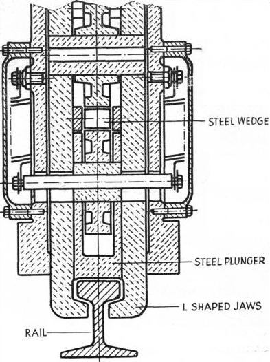
The principle underlying this system is two-fold. It consists in effecting an upward pressure upon the two lower surfaces of the rail-head by means of two L-shaped jaws, while at the same time a steel plunger presses vertically upon the upper surface of the rail-head, which is thus tightly gripped from three sides. The combined pressure from below and from above is so powerful that even on the steepest gradients a loaded carriage is brought to a standstill almost instantaneously.

THE RAIL-HEAD BRAKE exerts both an upward and a downward pressure simultaneously. The two lower surfaces of the rail-head are gripped by L-shaped Jaws, and its upper surface by a steel plunger. Braking is effected by the action of a steel wedge having its tower surface on the plunger and its upper surface touching a steel bar connecting the upper ends of the L-shaped jaws.
The braking device is contained in a casing which is suspended from the underframe of the carriage in such a way that the rail-head is enclosed between the L-shaped jaws and the plunger with an interspace around the rail-head of about half an inch. The gripping of the rail-head by the two jaws and by the plunger, is effected by a steel wedge having its lower surface on the plunger and its upper surface touching a steel bar which connects the upper ends of the L-shaped jaws. When the steel wedge is pushed forward horizontally between the steel bar and the plunger, it lifts the bar and therefore the jaws which press against the rail-head from below. At the same time the wedge presses the plunger downwards on the rail-head's upper surface. In the normal position, when the train is in motion, the plunger and the jaws are kept at a distance from the rail-head by springs. The brake works either by hand or automatically. For braking by hand a hand lever operates the brake by means of a helical gear, which is connected with a geared axle operating a similar brake on the second rail. The automatic installation consists of two identical brakes which are placed between the wheels on one side only of the carriage. They act mechanically in the same manner as the hand brake, but they are operated by an automatic device. This comprises a tank from whence oil, compressed at seven atmospheres, is driven through pipes and sealed chambers to two cylinders, the pistons of which press the steel wedges of the two brakes forward in the manner described. By making use of the difference in pressure between the oil under pressure and another circuit of oil, distributed by a pump (operated by the motion of the carriage) at atmospheric pressure, a valve is kept tightly closed, and the brakes arc in normal position.
The traction rope is connected with a lever, the upper arm of which compresses a double helical spring connected by a wire to a lever which causes the opening of the valve. The oil under pressure flows into the cylinders, and moves the pistons which push the steel wedge forward.
This automatic action occurs when the traction rope breaks, and the tension, therefore, fails. The lever is released, freeing in its turn the spring from its compressed position so that the wire and the subsequent levers are pulled. The automatic brakes of the two cars forming one train are electrically connected, so that the brakes in both cars act simultaneously.
Although this arrangement sounds very complicated it is in reality a most simple one, and acts almost instantaneously.
The Japanese authorities carried out some interesting tests on taking over the line from the constructors. The carriages were loaded with 140 bags of sand weighing nine tons, so that the total weight of each loaded carriage was about eighteen tons. The upper car of a train was made to descend the gradient of 1 in 2 at the normal speed, when the hand brake was applied. The car stopped in two and two-fifth seconds within three and a half yards. Another test was made with a loaded car at standstill on the same gradient. The tension of the traction rope was suddenly released, such as would occur with a fracture. The car moved forward ; the automatic operation of the brakes, caused by the supposed fracture of the traction rope, checked the car within one second and within one yard. Tests were also carried out with a loaded train.

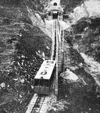
UPPER TERMINUS of Mount Rokko San Cable Railway. The difference in level between the upper and lower termini is 1,614 ft. The average gradient is 1 in 3½, and the maximum gradient 1 in 2. The laying of the track entailed the boring of tunnels and the erection of concrete viaducts.
You can read more on “Aerial Railways”, “The Railroads of Japan” and “Travelling by Train in China” on this website.


