
© Railway Wonders of the World 2024 | Contents | Site Map | Contact Us | Cookie Policy


New Italian Cableways
Conquering the heights by aerial transport
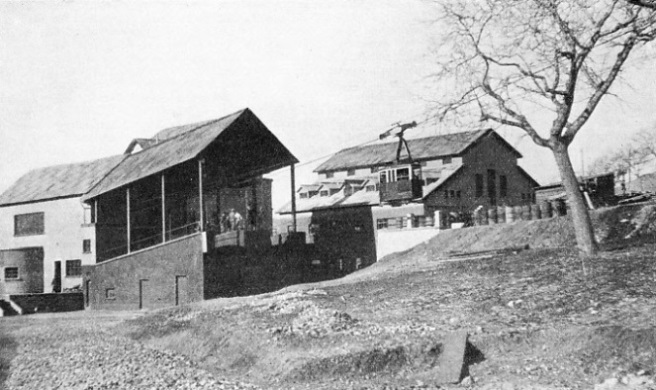
THE LOWER STATION of the Gran Sasso Aerial Ropeway. This station is near Assergi, ninety-
WE are accustomed, when talking of Italy, to visualize a country of eternal sunshine and warmth. It seems almost incongruous and disappointing to find in the centre of Italy, within easy motoring distance of Rome, a high mountain range scored by perennial glaciers. This is the range of the Abbruzzian Apennines, where for nearly six months of the year wide stretches of the mountain slopes are covered with deep snow which attracts thousands of ski enthusiasts.
The great development of skiing which has taken place during recent years, in Italy as elsewhere, has been responsible for the opening up of new districts, which are best reached by that most modern means of transport — the aerial ropeway. In this chapter more attention will be given to the mechanical side of these railways through the air. The two Italian ropeways about to be described are the latest to be completed at the time of writing. Although they are both built on the same system (Ceretti and Tanfani), they present an interesting contrast as typical examples of the long-
The Gran Sasso is the highest group of Italian mountains south of the Alps. It is situated almost in the centre of the Apennines. The Apennine range begins above Ventimiglia, the frontier town on the Italian Riviera, sweeps westward in a curve behind Genoa, and turns south-
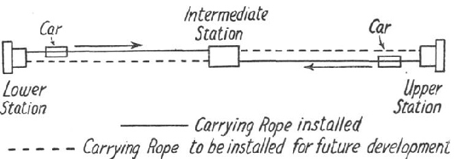
THE GRAN SASSO LINE is divided into two independent sections. Each section is fitted with its own carrying rope, but there is only one traction and brake rope for both. At the intermediate station passengers change from one car to another. The arrangement doubles the capacity of the ropeway, and if required the single lines can later be duplicated, as shown in this sketch.
The ropeway has several interesting features. The engineers have adopted a novel plan, which, while reducing the initial outlay, permits the doubling of the capacity of the line at a small additional expense. The line has accordingly been divided into two independent similar sections with an intermediate station. Each section has its own independent carrying rope, but there is only one traction and brake rope for both sections. The cars travel on the “jig-
The carrying ropes are supported by five steel lattice supports, three of which are in the lower section. The maximum span of 1,012 ft. is in the upper section. The height of the supports varies according to their position, the maximum being 102 ft. The carrying ropes of the two sections are equal in length. The ropes of the lower and the upper sections are anchored in the lower and upper terminus stations respectively. Both are kept taut by tension counterweights suspended in wells, which have been built in the intermediate station. The carrying rope has a diameter of 2 3/64 in. and is made up of 133 wires. The breaking strength is about 190 tons.
The traction rope consists of six strands of nineteen wires over a hemp core and has a diameter of 15/16 in, the breaking strength being 37 tons. It is fixed to the cars at the ends facing the upper station. The ballast rope of six strands of twelve wires has a diameter of 25/32 in. and is fixed at the rear of the cars. The braking rope is a characteristic feature of the Ceretti and Tanfani system. It forms a closed circuit between the upper and lower termini. It is wound round a separate pulley in the lower station, and the tension is kept constant by counterweights at the upper station. The braking rope moves at the same speed, and in the same direction as the traction rope, running through the brake clutches, which are normally kept open by the effect of the tension of the traction and ballast ropes. When for any reason the tension of either of these two ropes falls below the predetermined limit, the brake clutches close tightly on the braking rope. This action simultaneously operates the electro-
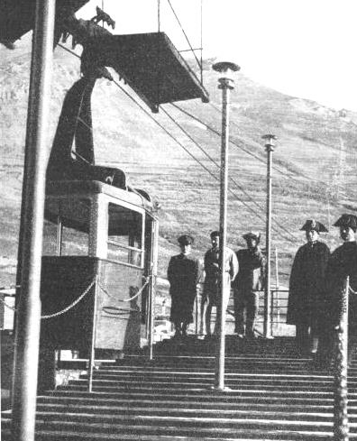
THE DEPARTURE PLATFORM of the Gran Sasso Aerial Ropeway at the lower terminus. Each car seats twenty passengers and a driver. The stations and the cars are connected by telephone. If the wind speed indicators show a pressure of more than 4.1 lb. per sq. ft. the service is discontinued. The braking system is automatic.
The lower station comprises a shed with the arrival and departure platforms, and an adjoining building which contains the waiting-
The upper station houses the driving machinery, which is arranged in a hall 90 ft long and 30 ft. wide. The carrying, traction, and braking ropes are anchored here in the same way as in the lower station. The driving plant consists of the motor, connected with the geared driving shaft, which engages through the gear transmission the main pulley and the counter pulley. Two sets have been installed, one acting as reserve. Each set is equipped with two hand brakes, two electro-
The electric installation consists of two similar groups which are used alternately. Each group comprises a 110 h.p. diesel motor, a D.C. dynamo at 200-
Particular attention has been given to the safety and braking arrangements, and every possibility of mechanical failure and of human error has been considered.
The electro-
In each of the three stations, and on the steel support, special wind-
The passenger cars are built of light metal alloy. The upper part has large sliding windows which permit an uninterrupted view. The folding door opens inwards and is fitted with an automatic safety lock that closes when the car starts moving. A special steadying device attached to the suspension of the car prevents excessive oscillations and ensures perfectly smooth running. On the outside of the cars basket-
A trap-
The Aerial Ropeway of the Gran Sasso was opened for traffic in October 1934. It may be regarded as a typical and up-
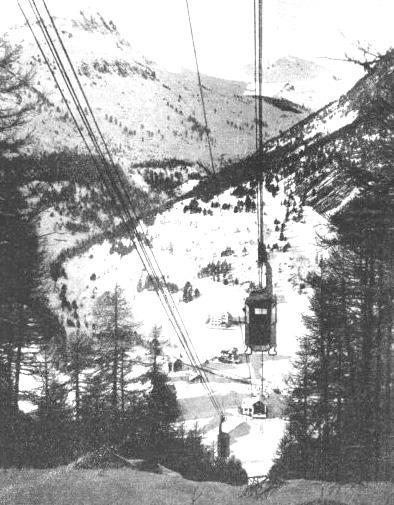
THE CLAVIÈRES CABLEWAY has been constructed on the “jig-
Not less interesting is the Aerial Ropeway from Clavières to Pian del Sole. This also is built on the Ceretti and Tanfani system, but its short length has made unnecessary the division into two sections and the erection of an intermediate station.
Clavières is a small Alpine village and one of the highest inhabited places in Italy. It lies at an altitude of 5,774 ft. above sea-
People speak in Italy of “the snow of Clavières” in the same manner as they speak of the “sands of the Lido”, or of “the blue waters of Capri”. There is a good reason for thus describing the superlative quality of the snow of this region. The natural causes responsible for its excellence are not known, as the matter has never been scientifically investigated. We can only surmise that it may be due to some unusual combination of the exhalations of the soil, of the chemical composition of the evaporating water, which turns to snow, and of a particular degree of atmospheric humidity. But whatever the causes, the snow of Clavières is considered to be the best that can be found on the southern slopes of the Alps.
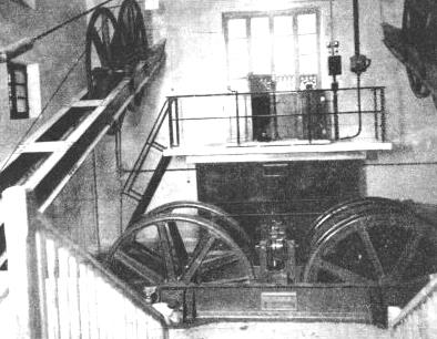
PART OF THE MACHINERY at the lower terminus of the Clavières line is shown here. A three-
Expert skiers are very particular about the quality of the snow, and it is a surprising and fascinating experience for the beginner to listen to a conversation of a group of expert skiers on the merits of this or that “run”. It was, therefore, only natural that when the line from Clavières was projected the advice of several famous expert skiers was sought to ascertain the best run to which the aerial ropeway should be brought. The decision fell on the Pian del Sole — the Plain of the Sun. It was here, in seemingly eternal sunshine, that the upper station of the line was built.
The length of the aerial ropeway is 973 yards. The difference in level between the two stations of Clavières and Pian del Sole is 984 ft. The driving plant is installed in the lower station. The upper station contains the tensioning devices for keeping the ropes taut. Along the line two intermediate steel lattice supports carry the rollers over which the traction and brake ropes run, and the shoes over which the carrying rope is laid. The rollers have, as usual, interchangeable rubber lining so that the wear and tear of the ropes shall be kept at a minimum. The steel supports are anchored in huge concrete blocks that are set deeply into the solid rock.
A Rail-
 The ropeway is built on the “jig-
A CLOSE-
The passenger cars seat sixteen passengers and the driver, and are built of light metal alloy. Their construction is otherwise identical to that of the cars on the Gran Sasso line, with the exception of the arrangements for carrying the skis. Each car has at the rear a large metal basket which occupies its whole width. The normal speed of the cars is 14 ft. 9 in. per second, and the journey takes three and a half minutes. A hundred and sixty passengers can thus be carried per hour in either direction.
The success of the Clavières aerial ropeway, which has attracted large numbers of visitors, has led the Italian State Railways to provide a special rail-
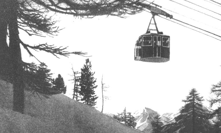
ON THE AERIAL LINE between Clavières and Pian del Sole in Piedmont. The length of the aerial ropeway is 973 yards and the difference in level between the two stations is 984 ft. The normal speed of the cars, which seat sixteen passengers and a driver, is 14 ft. 9 in. per second. The trip takes three and a half minutes.
You can read more on “Aerial Railways”, “Miniature Railways” and “Railway Curiosities”
on this website.