© Railway Wonders of the World 2012-


England’s First 4-6-0
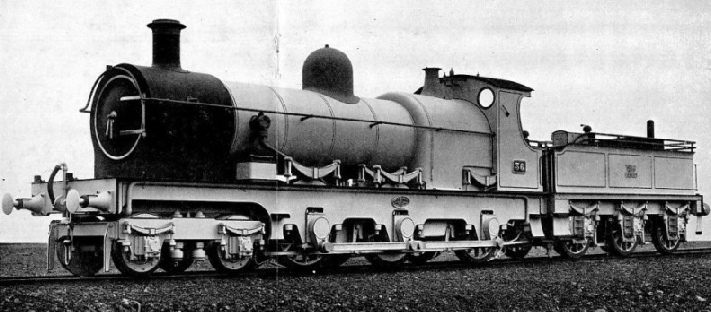
The Story of G.W.R. No. 36

ENGLAND'S FIRST 4-
This engine was not the first 4-
Broadly speaking, No. 36 was basically a much enlarged “Duke” class 4-
The boiler was quite a large one, pitched 7 ft 8¾ in. above rail level and made in two rings, the diameters of which were 4 ft 6 in. and 4 ft 7 in. outside; the diameter outside the clothing plates was 4 ft 10½ in. The distance across the firebox clothing plates, at the boiler centre line, was about 6 ft 6 in.; the top of the casing was semi-
The barrel was 14 ft long and contained 150 Serve tubes 2½ in. in diameter; these were special tubes, much favoured by William Dean at that time, because their insides incorporated a number of ribs which were supposed to extract more heat from the firebox gases and so enhance the heating surface. They did that all right, but in due time they developed other and less desirable habits that were not calculated to add to their usefulness or popularity. They were exceedingly stiff and rigid and, under the effects of alternate expansion and contraction, their movements were apt to get well out of phase with similar action in other parts of the boiler. The result was that they were inclined to play old Harry with the tubeplates, an effect that seriously curtailed the life of the boiler. Because of this, Dean finally confessed himself beaten and gave up using Serve tubes.
The heating surface of No. 36 was 1,517.89 sq. ft, made up of 1402.06 sq. ft for the tubes and 115.83 sq. ft for the firebox. The grate area was 30.5 sq. ft and the working pressure 165 p.s.i. The wheelbase was 25 ft divided into 5 ft 6 in. plus 4 ft 10 in. plus 6 ft 8 in. plus 8 ft, while the wheel diameters were, bogie 2 ft 8 in., and coupled 4 ft 71 in. The overhang at the front was 2 ft, and at the back 6 ft.
The engine weighed 59 tons 10 cwt in working order, 12 tons 6 cwt resting on the bogie, 15 tons 12 cwt on the first coupled axle, 16 tons 11 cwt on the driving axle and 15 tons 1 cwt on the trailing axle.
The bogie was of interest because it was of swing-
No. 36 was known as “The Crocodile”, possibly because her large size, small wheels and outside coupling-
No. 36’s sphere of operation was confined to territory west of Swindon. She must have been quite an impressive sight. She was finished in all the usual G.W.R. finery of the period, dark green for the boiler, cab and tender body and deep, rich Indian red for frames, splashers and wheels, all except the wheels with the usual black and orangey-
The official particulars give the tender capacity as 2,600 gallons; but the tender looks exactly like the standard 2,500 gallon type, judging by photographs. Possibly, there was an additional tank, or well, under the body, to augment the water capacity by 100 gallons. In any case, it was among the earliest G.W.R. tenders to be fitted with water pick-
When first built this engine was fitted with pumps, driven from the crossheads, for feeding the boiler, and had massive clackboxes with their very conspicuous copper piping, mounted at the sides of the boiler barrel, just behind the smokebox. After a few months, this arrangement was altered, the pumps being replaced by steam and exhaust injectors and the clacks removed to positions on the back of the firebox inside the cab. The holes in the boiler barrel were plugged, and those in the outer clothing were covered by neat brass caps as shown in my drawing.
No. 36 was the first G.W.R. 4-
The design of this engine was not adopted as standard, and the engine was withdrawn for scrapping in December, 1905, after a life of eight years, during which she ran some 171,430 miles. Her total length, over buffers, was 57 ft 10¾ in. — quite a monster for her time. The grate was 5 ft 10 in. wide; the width of the footplating was 7 ft 8 in.; the length of front bufferbeams was 7 ft 7 in.; the distance between buffer centres was 5 ft 9 in., and the outside frames, usually ¾ in. thick, were generally 6 ft 7 in. apart, inside, while the distance over the treads of footsteps was 8 ft 2¼ in.
You can read more on “The Coming of the Ten-