Construction and Maintenance of the Railroad
TRACK TOPICS- 1

EVERY FOOT OF TRACK IN BRITAIN that carries passenger trains is patrolled daily to detect possible flaw.
OF all the varied and innumerable constituents that go to make up the railway, the so-called “permanent way” is probably the least permanent of any. The word permanent was probably used in the early days of railway construction to distinguish the “permanent” track, then under construction, from the temporary track that was used in the meantime. But in truth the permanent way is anything but permanent.
Rails gradually wear away, owing to the constant abrasive action of the wheels on their upper surfaces; in tunnels corrosion still further reduces their life. Other track constituents similarly wear out; sleepers, in the course of time, rot or split; the ballast gets dirty and fails to give efficient drainage. Periodic renewal of the permanent way, either in part or as a whole, is always, therefore, in progress.
Long before the advent of the first locomotive, pioneer railway tracks had come into existence. The lines of parallel, flat-topped stone blocks that have been discovered along the routes of Roman roads show that these famous road-builders appreciated the virtue of providing as smooth and solid a road surface as possible for their chariot wheels. As far back as the sixteenth century tracks similarly laid with parallel baulks of timber had come into use in the vicinity of collieries in the county of Durham; for the colliery owners found that their horses could pull far greater loads if the wheels of their wagons ran over a flat, true surface of this description, rather than over the rough roads of the period.
But the wagon wheels gradually indented and destroyed the timber, and the next logical step, early in the eighteenth century, was that of laying iron plates over the upper surface of the timber. The business of keeping the wagons on the tracks was at first left to the dexterity of the horse drivers, and the next development, therefore, need occasion no surprise.
On a tram-road at the Nunnery Colliery, near Sheffield, iron angles were used over the timber baulks, instead of flat plates; these parallel angles were laid back to back, with a distance of about 5 ft between them and the flat portions of the angles, on which the wagons ran, pointing outwards. The upturned portions kept the wagon wheels from straying off the track; they were, in effect, the first step towards “gauge”. It is interesting to recall that the title of “plate-layer”, which was applied until recently to the men responsible for the laying and maintenance of British tracks, descended from those who, in those pioneering days, were sent out to lay the primitive “plate-ways”.
But the surface of such lines as these, from the running point of view, was still far from perfect, and it is to William Jessop, the engineer of a tram-line near Loughborough, Leicestershire, that we owe the idea which underlies track construction of to-day. In 1789 he laid a cast-iron rail which had a substantial upper flange, to carry the wheels, and a broad foot at one end, which was provided with a hole for spiking down to the sleepers, and at the same time formed a socket to accommodate the end of the next rail. These Jessop rails were only a yard long, but the principle had thus been established of lifting the wheels off the ground level, and of running them on the upper surface of the rails; for this purpose, of course, flanged wheels were necessary, instead of the ordinary wagon wheels, which had been used up till that time.

MAN POWER. Laying a new 60 ft rail, which weighs over 17 cwt. Assistance in manipulation is afforded by the rail-lifting apparatus seen across the track in the background.
It is to this transfer from the plate-ways, with their angle-plates, to the rail and the flanged wheel, that we can probably trace the origin of the singular measurement of 4 ft 8½ in, which has become the standard track gauge in Great Britain and so many other countries. Originally, in all probability, the wagon wheels were roughly 5 ft apart, and the upturned flanges of the angles were laid at slightly less than this distance from one another. But the change to flanged wheels transferred the measurement from the outsides of the two angles or rails to the insides; and the deduction from 5 ft of the width of two heads of the diminutive rails used in these early days brought the width of track down to the uncomfortable figure of 4 ft 8½ in, with which we are now saddled.
As the first locomotives sent to America were of British origin, America also standardized 4 ft 8½ in as its railway gauge; the same figure also obtains generally on the continent of Europe, and explains why it has been possible for the British locomotive “Cock o’ the North” of the LNER, to run trials on the French railways; also why wagons can be run direct from Great Britain to destinations abroad by way of the Harwich-Zeebrugge train-ferry. Only in Russia, with a gauge of 5 ft, and Spain and Portugal, with 5 ft 5¾ in, is there a difference of gauge from the normal.
The Gauge Muddle
In Great Britain, Isambard Brunel departed from the standard by laying a gauge of 7 ft, but ultimately it had to be abandoned, at enormous expense, because of the impossibility of running through coaches or wagons between the GWR and any other system.
It is in Australia, probably, that this break of gauge difficulty is seen in its most acute form. Each State began to lay its railways on the gauge best suited to its own needs, with the result that the railways of Western Australia and Queensland are of the 3 ft 6 in gauge; those of New South Wales and the Trans-Australian Railway from Kalgoorlie to Port Augusta are 4 ft 8½ in; and those of South Australia are partly 5 ft 3 in and partly 3 ft 6 in. Consequently, any through journey across Australia, say, from Fremantle or Perth in Western Australia to Brisbane in Queensland, involves a number of changes of train, owing to break of gauge.
In India, and also in Argentina, a gauge of 5 ft 6 in is in use on all the principal lines and is of considerable value, permitting more ample development of rolling stock - particularly of locomotives - than is possible on a gauge of 4 ft 8½ in. Ireland differs from Great Britain in having standardized a gauge of 5 ft 3 in. In many parts of the world a narrower gauge, laid in the first instance from motives of economy, has now become standard; South Africa and Japan, for example, use a gauge of 3 ft 6 in, and many thousands of miles of track in other countries are laid either with this width of track or the closely associated metre gauge.
To revert to early developments, we find that before the nineteenth century had dawned - and therefore before the first steam locomotive on a track had ever run - rails were being cast in such a way that they could be held in independent cast-iron chairs, wedged in position with “keys”; and the chairs themselves were being spiked down to transverse instead of longitudinal sleepers, so that the first elements of present-day track had already appeared.
As soon as any appreciable weights came to be imposed on the tracks, it was found that cast-iron was a very poor material for the purpose; not only did it wear away rapidly, but its brittleness also caused constant fractures. So the next step was to produce a rail of wrought iron, rolled instead of cast, and much better fitted, by its tough and fibrous character, to withstand the wear to which it was subjected.
Then, as the weight and speed of traffic increased, it was found that wrought iron could not stand up to the work. Fort-unately, the coming of steel, with its remarkable properties of combined strength and resistance to abrasion, was of great help. The first steel rails on record were laid in 1857 on the Midland Railway at Derby; they proved their value by remaining in use for sixteen years at a location where it had been necessary to renew the iron rails every three months. At the earliest possible date, therefore, steel rails were used to replace iron on all railways then in existence.
The question is often asked as to how long a rail may be expected to “last”, but it is a question that does not admit of a precise answer. To a certain extent the reply depends on the rail itself, and whether or not it contains special toughening alloys or has been subjected to heat treatments designed to increase its wearing capacity.
Track-Testing
Beyond this, however, everything depends on the nature of the traffic passing over the stretch of line in which the rails are laid - on its weight, frequency, and speed; on whether the line is straight or curved; on whether the rails are laid in the open or in tunnels, where the combined action of moisture and sulphur may have serious corrosive effects; or in the vicinity of stations, where the effects of braking and acceleration will be felt; and on many other factors.
Rails in some sections of line, where a comparatively light and infrequent traffic is carried, have remained in use from forty to over fifty years; at some suburban locations in a city such as London the life may vary from two or three years to a matter of only months. It is in electrically-worked suburban tracks - with their dense train services, constant braking to stop and acceleration from stops, and motor-driven wheels of small diameter - that the destruction of the rail-head is most rapid, and renewal is most frequently needed.
There are various ways of measuring the extent to which rails have worn, and one of these is shown in an illustration below. “Plasticine” is used for this purpose, in a special hinged frame, which is closed round the rail, head and foot; when the frame is withdrawn, an exact impression of the rail is left in the “Plasticine”. The mould is then inserted in a kind of printing-frame, with a sheet of sensitized paper, and a print showing the rail section is thus obtained. In this way the wear of rails is observed and checked at regular intervals, and on the information thus obtained the time for renewals is decided.
Another development of importance has been that of section. Few British travellers on the continent of Europe can have failed to notice that the type of track in use differs entirely from that in Great Britain. There is a certain appearance of solidity about the British “bull-head” rail, securely keyed in its chairs, that seems absent from the Continental rail, with its flat foot gripped only at its edges to the sleepers. It was Charles Vignoles who invented the flat-bottomed rail, and it is often known by his name.

STEEL SLEEPERS. Experiments in the use of steel sleepers are being carried out on an extensive scale by the British railways. The success of these experiments depends largely on the resistance of the sleepers to corrosion.
The idea was gladly seized upon by the railway pioneers in undeveloped countries, for the use of the Vignoles rail meant that no more material had to be transported to the rail-head, probably, than the rails themselves, and the bags of iron spikes for securing them to the sleepers, which could be cut down from the adjacent forests. The use of bull-head rails would have added heavy loads of chairs and their wooden keys to this list.
The result has been that, in every country other than Great Britain (with the exception of a few individual railways) the flat-bottomed rail has become standardized for main-line use. It would be a mistake to suppose that present flat-bottomed track, as it is laid, for example, on the principal American and European main lines, is in any way inferior. No longer is the flat-bottomed rail merely spiked down direct to the sleepers.
To protect the timber by spreading the weight of the trains over a larger area of its surface, steel sole plates are used between the rails and the sleepers. Then the dog-spikes on important main lines have long since been replaced by big screws, passed through steel clips, which firmly grip the edges of the rails, and hold them so that the running faces of the rails are kept exactly to gauge.

A HALLADE TRACK-RECORDER is carried in the compartment of a passenger coach on express trains, and records - on the roll of paper revolved by clockwork - the oscillations of the coach during a test journey, thus indicating the condition of the permanent way.
MEASURING WORN RAILS by an ingenious appliance which consists of a frame holding a piece of “Plasticine”. The frame divides, and when removed from the rail, the impression obtained reveals any defects. Each impression is photographed and recorded.
As to weight, the rails used on certain Continental and most American main lines considerably exceed the heaviest rails used in Great Britain. The Pennsylvania Railroad of America, for example, has now standardized for main-line use a rail weighing 152 lb per yard, and on other lines 130-lb rails are freely used. In France the great PLM Railway has introduced a rail weighing 126 lb per yard. In Great Britain 95 lb per yard is the general standard, though a movement has begun towards the use of the 100-lb section in this country on lines carrying heavy traffic. Sections of this weight were used by the Midland and Great Northern Railways in earlier years, but were abandoned in favour of the 95-lb section.
The cross-section of the bull-head rail used in Great Britain resembles a dumbbell, though with this difference - that when new the head is larger than the foot. At first “double-head” rails were used, in which both head and foot were of equal section, with the idea that when a certain amount of metal had been worn off the top of the rail, it should be inverted in the chairs, and the same amount should then be worn from what was previously the foot. But it was found that the constant pressure of the rails on the chairs indented the foot during the first period of the rail’s use, with the result that, after it had been inverted, the depressions formed by all this chair-marking resulted in very rough riding.
The bull-head section was therefore devised, so named because the cross-section of the head is larger than that of the foot. The general plan is to allow the head to wear down before replacement until its cross-sectional area roughly equals that of the foot. The rail may then be used for a time in some subsidiary line or siding, if in sufficiently good condition, before being finally scrapped.
There are various kinds of wear. The worst with which the engineer must contend is that of the outside, or “high rail” on a curve, which gets cut away at an angle of 45 degrees or so by the horizontal pressure of the wheel flanges, resulting from centrifugal force as the trains round the curve.
As better methods of handling have been devised, both at the manufacturers’ works and at the railway depots and the line-side, so rails have grown in length. The earliest steel rails were mostly 24 ft or 30 ft long; since then they have grown progressively to 36 ft, 45 ft, and 60 ft, the last-named being now the general standard in Great Britain. For special purposes 90 ft rails are used, such as across level-crossings or bridges, where it is desirable if possible to dispense with rail-joints. America is behind Great Britain in this matter, most American rails being 33 ft or 39 ft long. But on the continent of Europe 24-metre rails (78 ft 9 in) are common, and Germany specializes in 30-metre rails (98 ft 4 in).
The Germans also do a great deal in these days in the matter of welding rails together into long continuous lengths. Hitherto it has always been considered essential to keep the lengths of rails down to a reasonable figure; and to leave between them an expansion space at a normal temperature of ¼ in, to allow for the expansion of the rails in hot weather. When temp-eratures have been extreme rails have often buckled out of shape, and caused derailments of trains, owing to the rails having expanded to a greater degree than permitted by these spaces.
But it has long been the practice to weld tram rails together in continuous lengths; tram rails, of course, are buried, only the top of the head showing above the road metal, so that they do not respond to temperature changes so much as the rail-way rail, but they are also very tightly held and unable to buckle in consequence of expansion.

TRACK-LAYING AT SPEED. The track-layer is lifting a complete section of worn track to pass back to wagons in the rear. A new section will next be brought forward and dropped into position. The machine is fitted with an electric searchlight for work at night.
The same principle is therefore being applied to railway rails in Germany, and welded continuous lengths up to 90 metres (295 ft) are becoming common. The most startling experiment in welding has been carried out in the Brandleite Tunnel, where the rails have been welded together in both tracks throughout practically the whole length of the tunnel, which is all but two miles long.
The Weakest Point
At a central depot the 30-metre rails were welded in triplets into 90-metre lengths, and, despite their length, were trans-ported on wagons for some distance over the main line. (Rails are considerably more flexible than might be imagined, and the precautions taken in loading were sufficient to enable the wagons so loaded to pass over cross-over lines.) The final welding was carried out on the site, and in this tunnel there are now four rails, which are continuous for a distance of 2,640 metres.
Welding the rails together reduces the number of fishplates, but this is not the only reason that rails are being lengthened. The rail-joint is the weakest point in the track, and as the number of joints is reduced the cost of maintaining the line is lowered, and the riding of the trains is improved. It is the gap in the rails at the joint that gives the trouble. Inventors have devised new types of rail joint by the hundred, but none has solved the problem. The most obvious solution to the problem seems to be that the rails should be cut at the ends on the skew instead of on the square; this has been tried, but it makes very little difference.
The principal weakness of the joint is that the rail-end off which a wheel is running bends downwards under its weight, and the wheel then runs on to the level end of the next rail ahead, tending all the time by these impacts to drive the rails forward; and, almost imperceptibly, the rails do very gradually move forwards. The phenomenon is called “creep”, and at some locations is very troublesome. From time to time the rails have to be pulled back to their normal positions.
Lately in Great Britain the problem of the joints has been simplified by cutting the fishplates (which join the rails together) from 18 in in length down to 10 in, and securing the rails by one bolt at each rail-end, instead of by two; this enables the adjacent sleepers to be brought much closer together, so that the joint has considerably better support than before.
The bull-head rail rests in cast-iron chairs, which, in standard British practice, weigh 46 lb apiece.
Between two upstanding jaws the rail stands, with its foot securely housed under the lower one, while between the “web” of the rail (which joins head and foot together) and the outer jaw of the rail, a key of compressed oak or teak is tightly driven. Every now and then keys work out of position, and fall on to the ballast; and the surfaceman, driving them in with his hammer, is a familiar sight on the railway track.
Many ingenious patents have been devised to produce keys which will not drop out in this way, but the patentees have overlooked one important fact. It is that in any event every mile of railway track over which passenger trains run must be “walked” daily, in order to ensure that every detail is in perfect order for the safe running of trains.
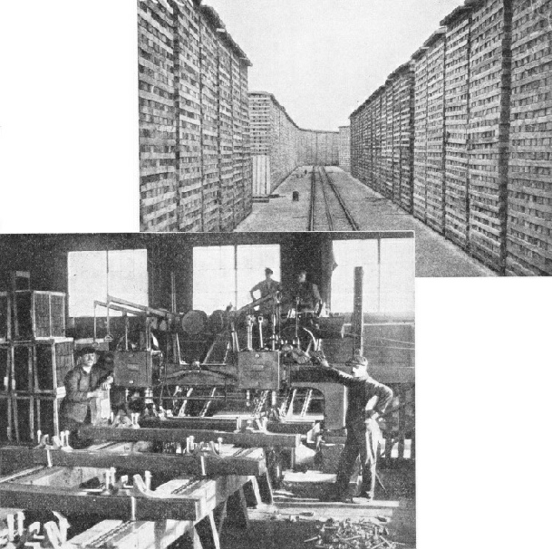
TIMBER ALLEY. Sleepers are stacked at railway creosoting depots to be seasoned before the creosoting takes place.
A CHAIR-SCREWING MACHINE which simultaneously drives home six large chair-screws to secure chairs firmly to sleepers, is seen here at the London and North Eastern Railway's works at Boston, Lincs.
The line is divided into sections, and each section has its gang of men responsible for this supervision. Driving a key here and there in the course of these perambulations is a minor matter, and, in effect, costs nothing, whereas most of these patent keys would be very expensive, and the users would be no better off in consequence. Incidentally, in some country areas where traffic is not dense and the gangs of surfacemen have considerable lengths of line to supervize, they are provided with motor-driven trolleys to assist them in covering rapidly the ground which they have to patrol.
The rail seat of the chair is rounded to a radius corres-ponding with that of the underside of the rail-foot, which is 12 in. The jaws hold the rail tilted slightly out of the vertical; this tilt, which is 1 in 20, is for two reasons. It holds the centre-line of the rail exactly at right-angles to the face of the wheel-tyre, which is coned; and it also ensures that the rail will be safely in position even though all the keys should be out throughout its length.
The flat base of the chair helps to distribute the weight of the trains over as large an area of the sleeper as possible, and the life of the sleeper is further preserved, and the running of the trains is quietened, by the interposition of a felt pad between the chair and the timber. Three large galvanized screws, each weighing 1½ lb, secure each chair to the sleeper, except on the Great Western Railway, which uses two bolts passing through the sleeper, and held on the underside by fanged washers that bite into the timber,
The supply of timber for sleepers is a problem. Most of the sleepers used on British lines come from the countries bordering on the Baltic, and are of fir, 9 ft long by 10 in wide by 5 in deep. Before use they require creosoting as a protection against rot, and for this purpose each sleeper is made to absorb from three to six gallons of creosote oil.
The depots at which this creosoting is done are, with their huge piles of sleepers, familiar sights to travellers; they may be seen on the GWR at Hayes, in Middlesex; on the LNER at Boston, Lowestoft, and West Hartlepool; on the LMS at Beeston (Nottingham), Northampton, and Ditton Junction (Widnes); and on the Southern Railway at Redbridge, near Southampton.
The seasoned sleepers are run on trolleys into long cylindrical tanks, which are then tightly closed, after which the air in the tank is exhausted and creosote is pumped in under pressure until the desired quantity has been absorbed. At the same depots the sleepers are now “chaired” by automatic machinery. One machine shapes two flat seats on the timber to receive the chairs, and at the same time bores the six holes for the chair-screws; the chairs are then dropped into their places, wooden ferrules are inserted in the holes, and the screws into the ferrules, after which the screwing home is done mechanically. So the sleepers are sent out chaired and in readiness for laying in the track.
Various substitutes for timber sleepers have been tried; in some countries they are essential. The voracity of the white ant, for example, would soon terminate the life of wooden sleepers laid in countries where this hungry pest is found. The commonest substitute for timber is the steel sleeper, pressed while hot out of a steel plate into the shape of an inverted pea-pod, and with clips forced out on the top to engage the feet of the flat-bottomed rails, which are held in position by tapered steel keys. Other types of steel sleeper, as well as cast-iron “pot” sleepers - inverted bowls of cast-iron on which the rails rest, kept at the correct gauge distance apart by steel tie-bars - are used abroad; but none of these substitutes has made much headway on the railways of Great Britain.
Smooth Riding
The controlling factor in a country with a climate like that of Great Britain depends on how the thin steel sleeper will stand up to corrosion, especially when laid in such ballast as broken blast-furnace slag, which contains sulphur; and unless the sleeper gives a longer life in proportion to its increased cost, it will be a bad bargain. Another difficulty is that steel sleepers cannot be used where electrical track-circuits are employed in connexion with the signalling.
Experiments are being carried out in Great Britain with steel sleepers, and in the course of time much more information about these latest experiments will available. Concrete sleepers have been tried, but with unsatisfactory results; they are very cumbersome to handle, and cannot stand up to their work without cracking as a result of vibration.
Ballast is an important component of the railway track. By the way in which it is packed under the sleepers it governs the level of the rails, and has a strong influence on the relative smoothness of riding. It maintains the sleepers in position, especially on curves, and on it the permanent way depends for support as well as for “line”. Most important of all, it serves to drain away the surface water from the track. The gravel and cinders of earlier days have given place largely to granite and to broken slag. The latter has been obtained in enormous quantities by crushing the contents of the vast slag-heaps which disfigure the neighbourhoods of our ironworks and steelworks; tipped as waste, they have thus been put to good use, and some of the heaps have nearly disappeared in consequence.

ON THE CPR SYSTEM. Flat-bottomed rails are employed on the Canadian Pacific Railway, and are secured to each sleeper by three large screws. This photograph shows the “Trans-Canada Ltd” express entering Windsor Street Station, Montreal.
For one mile of modern British mainline track the following materials are needed:
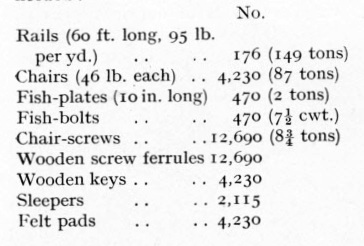
To these figures it is necessary to add the ballast, of which roughly 3,500 tons are needed for every mile of double track.
Relaying of railway tracks in need of renewal proceeds each year according to an ordered programme. When relaying is in progress signs are erected at the side of the line to warn drivers that they must reduce speed. First comes a horizontal board, painted green, which is pointed at one end and fish-tailed at the other, and at night shows white and green lights side by side; this is erected at a point half a mile from the beginning of the relaying. An additional warning is generally given by placing detonators on the line well clear of the point where the relaying is in progress. Where it commences, a large “C”, on opal glass, illuminated at night from behind, is erected on a pole, and a “T” is placed at the farther end of the work for “Terminates”.

A CHAIRED TRACK. The rails rest in cast-iron chairs and are firmly held in position by wooden wedges or “keys” driven in the direction in which trains will run.
STEEL FISH-PLATES connect every pair of rail ends. The later type is shorter than these, and has only two fish-bolts. To allow for expansion a gap of ¼ in is left between the ends of the rails.
The old track is stripped with the utmost speed; no time is wasted in unscrewing old fish bolts, but the heads are knocked off, the plates are removed, the rails are lifted out, and the old sleepers are dragged from their places. Then the new chaired sleepers are pulled into place, the rails dropped into position, the fish-plates attached and the fish-bolts screwed up, the keys driven in the chairs, and the rails drawn approximately into line. Traffic can now be resumed, but weeks may elapse before the track has been “lined up”. On curves there is the additional operation of super-elevating or “canting” the track - that is, lifting the outer rail to a higher level than the inner by packing up the sleepers accordingly, to counteract the influence of centrifugal force. The higher the speeds likely to be run, the more must be the degree of super-elevation.
In these days a certain amount of track relaying, and much pioneer track-laying, is done by special track-laying machines. When these are in use for relaying purposes, the preliminary operations on the site are confined to removal of the ballast and unscrewing the fishplates; the machine then lifts complete lengths of track - rails, chairs, and sleepers as one unit - and drops new units bodily into position.
These new units are stored on flat wagons behind the track-layer, and by an ingenious conveyer arrangement are brought forward from the train to the projecting crane-arm of the track-layer, while the lengths of old track are similarly passed down the train to the wagons for removal. A track-layer can operate at a speed of 240 yards of relaid track per hour, which is a considerable advance on ordinary manual methods.
Last of all, mention must be made of the method adopted for testing the condition in which any given length of track is being maintained. This is done by means of the Hallade machine, which is carried in an ordinary coach, and by a system of damped pendulums causes a pen to inscribe on a roll of paper, which is being slowly rotated by clockwork, an exact picture of the oscillations of the coach during the test journey. These records enable the engineers to see exactly where joints require packing up, or curves re-aligning.
The Great Western Railway goes even farther than this. A special bogie coach has been adapted for this track-recording and makes periodic journeys at the rear of ordinary express trains over all the main lines. Not only is a Hallade recorder carried in it, but the coach is equipped with automatic apparatus, the function of which, whenever one of the coach bogies moves by more than a predetermined amount in relation to the body of the coach, is to drop a splash of whitewash on the track at the very point where this excessive oscillation occurs.
You can read more on “From Iron Ore to Steel Rail”, “The Hurley Track-Layer” and “Switches and Crossings” on this website.