

The Great Apennine Tunnel
Engineering Marvels of the Bologna-
 THE NORTHERN PORTAL of the Great Apennine Tunnel, on the Bologna-
BEFORE entering into the details of the construction of the Great Apennine Tunnel itself, this page will deal briefly with the remarkable line on which it is situated. This railway is known as the Bologna-
The expression “direttissima” has no counterpart in English. It means “the most direct” and, when applied to a railway, indicates a line which has the maximum possible number of straight stretches, curves of very large radius, absence of level crossings and the minimum possible gradients. A “direttissima” is built without fear of natural obstacles through which it has to pass.
One is reminded of Tsar Alexander II of Russia, who, on granting the concession for the railway from St. Petersburg (Leningrad) to Moscow, prescribed the route by taking a ruler and drawing a straight line on the map between the two capitals of his empire. The “Direttissima” Bologna-
Italy’s peculiar geographical features have a great influence on the construction and working of her railways. With the exception of the northern parts, the country is a narrow strip averaging about ninety miles in width and extending for 600 miles in length. The Apennine mountain-
It must be remembered that whereas the northern parts of Italy are highly industrialized, the centre and south of the country are mainly agricultural. These latter provide the northern provinces with agricultural and dairy produce, and maintain at the same time a vast export of such products to all European countries.
All this traffic moves towards the industrial districts of Lombardy and Piedmont, and across the frontiers at Chiasso, Brenner and Tarvisio, and is carried over a system of lines which include the Florence-
This difficulty of reconstruction applied particularly to the Porretta line from Bologna to Florence via Pistoia. The line was built during the years 1856-
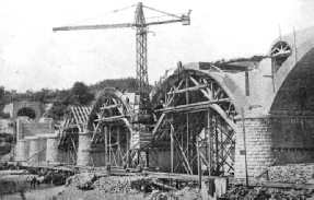 UNDER CONSTRUCTION. A fine masonry viaduct at Vado by which the “Direttissima” line crosses the River Setta. Each arch has a span of over 80 ft. There are forty bridges and thirty-
The route of the Porretta line was chosen not only for technical reasons but also for strategical considerations. The length of this line is almost eighty-
The inadequate capacity of this line was realized soon after its opening, and when Italy had been united in 1870, the ever-
Bold Planning
The project of the “Direttissima” Bologna-
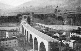 BUILDING THE BRIDGE over the River Setta involved the use of a special service bridge, which is shown to the right.
One of the results of the survey was to show that the original estimate of £6,000,000 would not be sufficient. A second provisional estimate for £7,000,000 was made. The provisional project was approved in 1911, and the elaboration of the definite project in all its details was taken in hand. Work on the line began in 1913. This was on the section between Bologna and Pianoro. The new route extended from Bologna to Prato, a station on the old line eight and three-
The “Direttissima” branches off the Bologna-
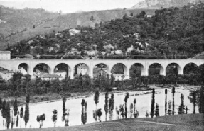 THIS VIADUCT over the Quercia River has nine arches of 65½ ft span and two of 39 ft span.
Having left this tunnel, the line enters the Setta Valley near the station of Vado and, having passed through another tunnel, negotiates the valley by means of an imposing viaduct-
All these viaducts, as well as the others on the line, are masonry constructions, for which Italians have always been famous. Beyond the station of Grizzana the line crosses the Farnetola Valley by a viaduct of twelve arches, of which eleven are 66 ft and one of 40 ft span. Here the Pian di Setta Tunnel begins, which has a length of 3,334 yards. On emerging from the tunnel the Brasinone river is crossed by a viaduct of three arches of 83 ft span and two of 66 ft, and after a short tunnel the Setta is crossed by a skew bridge with three arches of 66 ft and three of 40 ft. The line continues on the right bank of the Setta, crosses the river again over an oblique bridge of five arches of 40 ft span, and enters the Great Apennine Tunnel. From this it emerges near the junction of the rivers Fiumenta and Bisenzio, crossing the latter, and continuing on its left bank as far as the station of Vernio. After having crossed the Bisenzio twice the new line reaches the station of Vaiano and finally joins the old one at Prato.
The double track is laid with rails of 59 ft 1-
The new line is electrified on the direct current overhead system at 3,000 volts. The contact wires are fed by five trans-
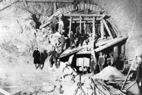
IN THE HEART OF THE TUNNEL is a station that enables fast trains to overtake slow traffic. The picture shows the station under construction. At this point the diameter of the arch is 56 ft.
It will be appreciated that considerable engineering feats were involved in these subsidiary operations.
The Monte Adone Tunnel has a length of 7,694 yards. The track runs straight with the exception of a length of 650 yards, which is on a wide curve with a radius of 2,200 yards. The tunnel was driven from both ends, and as no particular difficulties were encountered it was completed within five and a half years.
The Pian di Setta Tunnel has a length of 3,334 yards. It runs straight for about 1,820 yards, and then on a curve with a wide radius. Difficult conditions of soil were encountered and heavy emanations of methane gas (marsh gas) had to be overcome. Progress was slow, and thirty yards a day was the maximum. Work was begun in 1921 from the northern side, and in 1925 from the south. Advance headings met in 1928.
The “Direttissima” joins the old line, as previously mentioned, at Prato. The impossibility of enlarging the existing station necessitated the transfer of the station 700 yards farther south. A magnificent new station building was erected, and a large modem station was laid out.
The following figures give an idea of the magnitude of the construction of the “Direttissima”, the total cost of which amounted to £12,200,000 sterling. Embankments represent a volume of 192½ million cubic feet; seventy-
A Monument to Heroes
The line contains forty bridges, the total length of which is two and three-
But the most outstanding feature of the “Direttissima” is the Great Apennine Tunnel, the length of which is 20242·21 yards -
Seldom -
A monument erected on the square outside the station of Bologna bears ninety-
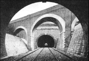
MODERN RAILWAY ARCHITECTURE. A “direttissima” line must be laid straight regardless of cost, and this involves much bridging and tunnelling. The Carmeto Tunnel on the Bologna-
The magnitude of the tunnel construction necessitated a vast amount of preliminary work. The nature of the soil through which the tunnel was to be bored had first to be investigated. Seven shafts were sunk at intervals to below the tunnel line, some of them to a depth of 1,300 ft. By doing this it was possible to ascertain the nature of the ground and its composition.
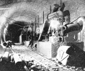
THE PROBLEM OF VENTILATION in a tunnel eleven and a half miles long is a vital one. Ventilation plants were installed at the two entrances to the Great Apennine Tunnel, and at the shafts. As the heading advanced, auxiliary ventilating machinery was installed within the tunnel.
The geological formation of the Apennines differs from that of the Alps. The Alps, where so many famous tunnels have been constructed, are of solid rock, and the boring did not present any particular difficulties. The Apennine mountains on the route of the “Direttissima” consist mostly of clay and sand schists. A worse soil for tunnel construction could not be found. It was clear from these surveys that construction would be very slow if it were undertaken in the usual way from both ends. It was, therefore, decided to create two further points of attack by sinking, about midway at Cà di Landino, two inclined shafts to the level of the tunnel. The two shafts were sunk at a distance of 400 ft from one another at an inclination of twenty-
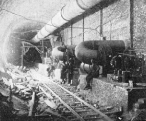
143,000,000 CUBIC FEET of air was driven into the tunnel each day. The auxiliary ventilating plants drew air from the main ducts and forced it through pipes of decreasing diameter to the workings. The fresh air was driven through one side of the tunnel, the used air escaping through the other.
In each of the shafts a cable railway was built for the conveyance of men and the transport of material. The trucks had a seating capacity for thirty men, and the trolleys were built for loads of 2·2 cubic yards. During the later stages of the construction a more powerful driving plant was installed; this was capable of hauling two trolleys each of 1·9 cubic yards. The hauling machinery was driven by three 75 hp motors of 720 revolutions per minute, each of the three pulleys being operated independently by one motor. The hauling ropes had a diameter of 1¾-
Before the construction of the Great Tunnel could proceed the problem of transporting all the machinery, material and plant had to be solved. Both entrances of the tunnel were a long way from any village, and farther still from any railway station. The existing roads were ordinary country roads, unsuitable for heavy lorry traffic. Furthermore, there existed the possibility of snowstorms or torrential rainfalls rendering the roads impassable. The solution was found in the construction of two service railways. One line of seventeen miles was built from Sasso, a station on the Porretta line, to the northern entrance of the tunnel. The second line of thirteen and a half miles was laid from Prato via the Bisenzio Valley to the southern entrance of the tunnel. The lines had a gauge of 3 ft 1⅜-
The rolling stock for the service lines consisted of fourteen steam locomotives and 216 trucks, by which two and a half million tons of material were transported. The cost of the two lines, including rolling-
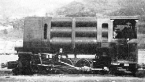
A COMPRESSED AIR LOCOMOTIVE used for the transport of men and material in the tunnel. The locomotive took in the compressed air from pipe-
The two service lines provided transport facilities only to the two entrances of the tunnel, and in order to bring the entrance to the inclined shafts at Cà di Landino within easy reach, an aerial ropeway was built from the northern tunnel entrance. The length of this ropeway was over five miles, and the difference in level between the two terminal stations 865 ft. The system of the aerial ropeway adopted was that of two carrying and one traction rope. The carriers had a capacity of 8 cwt, and the hourly capacity of the line was twenty-
At both entrances of the tunnel, and at Cà di Landino, the State Railway Administration built villages to house the thousands of workmen, engineers and their families. The villages were completely equipped; there were churches, schools, hospitals, maternity homes, kindergarten and cinemas. An aqueduct ensured the supply of fresh water, and electric light was supplied during the first few years by an oil-
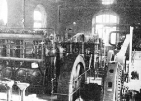
IN THE HALL OF MACHINERY, situated at the north entrance of the tunnel, a compressor plant supplied the compressed air for the locomotives and for the pneumatic hammers and drills.
The arrangements for the power supply were on a vast scale. Power was generated by eleven Diesel engines varying from 120 to 400 hp. Their total capacity was 2,540 hp, of which 600 hp were installed at the southern, and 720 hp at the northern entrance. There were 1,220 hp at the inclined shafts. Electric current was supplied over a 30,000 volts line from Prato, which had a length of twenty-
In view of the great length of the tunnel careful provisions were made to ensure the supply of fresh air to the farthest work-

STEMMING A FLOOD. This picture shows a wall of cement pierced by large pipes to disperse the water. A mixture of cement, wood-
On account of such large volumes of air it was necessary to divide the completed and lined sections of the tunnel by a temporary brick bulkhead running long-
For the transport of men and material inside the tunnel a narrow-
The Gas Menace
The presence of gas and the danger of explosions and fire continually worried the engineers in charge. Gas emanations were encountered during almost the whole time of the construction. The gas consisted of ninety-
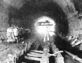
WATER WAS THE MOST STUBBORN ENEMY of the workers, and at one period the men worked waist-
The irruptions of gas were serious at times. Gas issued at the rate of 4½ cub ft per second at a high pressure. Fresh air had to be pumped at the rate of 1,350 cub ft per second to the danger spots to dilute the gas and render it harmless. The measures proved efficient, and there were only four explosions which caused any serious interruption of work.
Outbreaks of fire were more serious. One, at about three miles from the north portal, stopped work in the affected zone for seven months. This outbreak occurred during blasting, when an onrush of gas occurred and the timbering took fire. Despite all efforts the fire could not be extinguished. On the next day another heavy explosion occurred at the same spot. The ventilation bulkhead was destroyed for over 1,100 ft, as well as the cabin of the ventilation engineer. The upper and lower headings, which intercommunicated, were filled with heavy smoke, for, owing to the collapse of the bulkhead, the whole ventilation system had been damaged.
An heroic crew drove up on a compressed air locomotive to the burning timbering. The men flooded the area and checked the fire. Only then was it possible to ascertain that the lower heading had collapsed through the burning of the timbering. The temperature had reached 212 degrees. The temporary bulkhead was rebuilt, and also the ventilating cabin. Meanwhile, in the part of the upper heading where the fire continued unabated, three powerful hydrants protected the scaffolding which was erected to replace the wooden timbering with steel shores. Three fine-
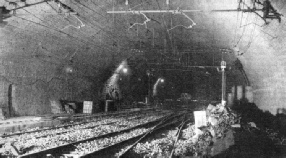
THE SOURCE OF POWER. Contact wires in the tunnel’s internal station. The overhead, direct-
Matters became worse through emanations of gas in the lower heading, they issued from a gas-
Fire and gas were not the only obstacles. Water was also a most stubborn enemy; it was present everywhere, seeping through the roof. through the sides, breaking through from underground caverns, spouting from the drill holes, bursting forth in the form of cascades at the rate of seventy-
A Stubborn Enemy
The original surveys had revealed that water would be met with in limited quantities, and at first this was so. Three reciprocal pumps had been installed, but with the progress of work more and more water appeared, and the original pumping plant had to be increased until twenty-
The most violent incursion occurred at a point 6,320 yards from the southern portal, when the waters broke through in the form of a cascade at the rate of 66 gallons per second. The canal built in the centre of the tunnel to collect the waters was insufficient; the lower heading was flooded and work interrupted. To stop the flow of the water a brick wall, 10 ft thick, was built and nine steel pipes of 6¾-
Despite all precautions water continued to trickle through over almost the whole length of the tunnel. In the Apennine Tunnel, where the line is electrified, even a small amount of water upon the overhead contact lines might cause serious trouble, and a dangerous situation would arise if the accumulated water were to freeze and icicles form, To waterproof the crown of the tunnel was a matter of vital importance. This was done over a width of 22 ft along the whole tunnel. A mixture of cement and sand, under pressure, was injected into a number of holes. The face was then roughened, cleaned with steel brushes, and washed by jets of water under pressure. All joints between bricks or masonry were cleaned of the adhering mortar by pneumatic tools. The waterproofing mixture was then applied in two coats to a thickness of 1-
The method of driving the tunnel was as follows: First a bottom heading, 13 ft 1½-
Although the geological survey had made it clear that the soil was of the most difficult kind for tunnel construction, the difficulties which were encountered on certain sections were never expected. The swelling clay soil had given trouble on the northern side, but heavy timbering, sometimes steel centring, the reduction in length of the working sections and the method of completing the lining overcame the difficulties.
At a point about one and a half miles from the north portal, however, a serious situation arose. The pressure of the swelling clay was greater than any timbering could withstand. The strongest pieces of 25-
A feature of the tunnel is the large passing station constructed about mid-
The section of the tunnel varies according to the nature of the ground. The radius of the crown extends from 14 ft 6-
The magnitude of the tunnel construction may be judged from the following figures: The excavated material amounted to 69 million cubic feet, the masonry work (linings) to 16 million cubic feet. The consumption of electric current was 110 million kilowatt hours, 981 tons of dynamite were used for blasting, an average of 8½ million cubic feet of compressed air was used for traction purposes and for driving the drills and pneumatic hammers; the average number of men working inside the tunnel was 1,300, and the average number working outside in the yards was 550. The cost of the tunnel was £5,100,000, or £252 per yard.

THE “ITALIAN” METHOD, used while boring through particularly difficult sections of the Apennine Tunnel, consisted of lining the circumference with rings of strong wooden key-
You can read more on
“Modern Construction in Italy”.