The Construction of and Performance Obtained from the Oil Engine
LOCOMOTIVES - 8
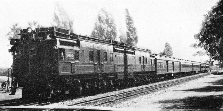
A DIESEL OIL-ELECTRIC LOCOMOTIVE on the Canadian National system. As early as 1925 an oil-electric car was run from Montreal to Vancouver without the engine being stopped at any point of the journey.
IN recent years the steam locomotive has experienced increasing competition, especially in connexion with the smaller trains and coach units, from the Diesel-engine-driven type. For certain types of work it has considerable advantages, and there is little doubt that in the course of time it may replace the heavier and more cumbersome steam-engine. It will take over the work of local rail-car passenger services, rail-buses, shunting locomotives of the smaller class, and rail-coaches for inter-town communication.
The oil engine is particularly suited for railway work abroad, in places where coal supplies are difficult to obtain and where oil fuel is more readily available. Apart from this advantage, however, there are more important reasons why the modern oil engine is superior to one of the steam type for the purposes previously mentioned.
In the first place, the type of oil engine used - the medium to high-speed Diesel - is more efficient than the best locomotive reciprocating steam-engine. It gives a much greater output of power from a given quantity of fuel consumed. To give an example of its superiority, it may be stated that if the same weight of oil were used to fire the boiler of a steam locomotive as that used in the combustion chamber of a Diesel engine, the latter would give at least six times as much useful horse-power as the former. It should, however, be pointed out, in fairness to the steam-engine, that the cost of coal is appreciably less, per pound, than that of fuel oil used for Diesel engines.
Despite this, the oil engine scores heavily in so far as fuel cost is concerned. And it has been the regular experience of users of Diesel-electric locomotives that one pound weight of fuel oil is equivalent, so far as power output is concerned, to eight pounds of coal. If, therefore, we consider the cost of fuel oil to be four times the cost of coal in this country, it will be seen that the oil locomotive will show a fuel bill of only one-half that of the coal-fired steam-engine.

THE POWER-UNIT. A six-cylinder Beardmore Diesel engine of this type drives Canadian National trains similar to that seen in the photograph above.
Secondly, the Diesel engine for the same power output weighs only a fraction of the weight of a steam locomotive, for it does not require the relatively large boiler, firebox, and tender of the steam locomotive. For the same reasons it occupies only a small proportion of the space required by the steam locomotive; it can be stowed away in a comparatively small compartment or even installed underneath the coach of a rail-car. Thus the rail-car, rail-coach and similar vehicles can be built much more compactly than when steam is used as the power unit.
The Diesel engine, on account of its lower weight and fewer units, is much cheaper in initial cost; indeed, it has been stated by one well-known manufacturer of Diesel rail-cars that, owing to the light weight and low cost of this type, it is possible to purchase several such vehicles for the price of a train of equal passenger-carrying capacity hauled by a steam locomotive.
Further, the Diesel type locomotive possesses the marked advantage of being able to start from the cold in a matter of seconds, whereas the steam-engine requires time for its boiler to heat up. Again, when a steam locomotive is employed on intermittent work, such as shunting, it is necessary to keep up the supply of steam, by stoking the boiler, all the time that the engine is idle, in order to be able to start at short notice; this means a wastage of coal. With the Diesel engine, on the other hand, the engine is stopped during such periods, for it can at once be started up again.
Those of our readers with experience of petrol engines, such as motor-car engines, may say that it is necessary to run such engines for a few minutes at least before they will “pull” properly. This is quite true of the petrol engine, but not of the high-speed Diesel type, for the latter, as is well known to drivers of commercial road vehicles fitted with the modern type of Diesel engine, will “pull” and accelerate almost immediately alter it has been started from the cold. The same is, of course, true of the Diesel engine used for railway purposes, so that it has a big advantage over the steam-engine.
Fourthly, the Diesel type locomotive requires much less room for the storage of its fuel than the steam type. Apart from the fact that it is not necessary to carry anything approaching the weight of coal of a similar output steam-engine, the oil fuel can be carried in relatively small fuel tanks placed in any convenient part of the train; it can, in fact, utilize what would otherwise be wasted space in or under the train.
Despite its numerous advantages, the Diesel locomotive is inferior to the steam type in one important respect-namely, that it requires a transmission system to convey the power from the engine to the driving wheels, and to deliver this power at the proper wheel speed. In the instance of the steam-engine the power is delivered direct, via the connecting rods and cranks, to the driving wheels, no intermediate transmission being necessary.
A further advantage of the steam-engine lies in the fact that it can exert a high driving, or tractive, effort on the wheels even at very low speeds. The Diesel engine, on the other hand, will only exert its maximum driving effort at a relatively high engine speed - namely, from 800 to 1,200 revolutions per minute. Thus the Diesel engine must be running at a high speed before it can start the locomotive from its stationary position, for it is a well-known fact that practically the greatest power given out by an engine is required for starting and accelerating purposes; and also for attaining its maximum rail speeds.
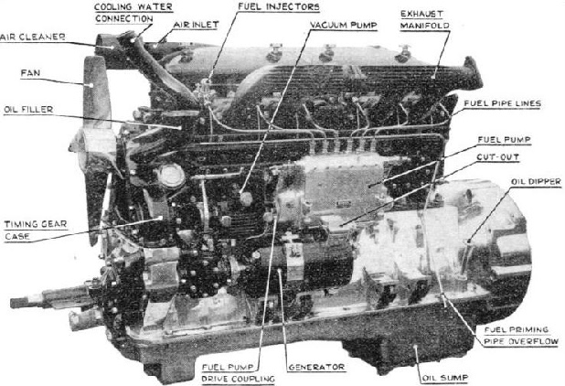
EXTERNAL VIEW of a 130hp, six-cylinder, high-speed Diesel engine, illustrating the main components.
It is therefore necessary to transpose between the engine and the driving wheels some form of gearing or transmission which will reduce the speed but at the same time increase the driving effort - or, as it is termed by the engineer, the driving torque or turning moment - to that required for starting the locomotive. In some forms of transmission it is also necessary to have a clutch for taking up the drive from the engine. Without going further into the subject at this stage, it will be evident that the necessity for such a transmission for starting, and also rail speed control purposes, not only adds to the cost of the Diesel locomotive, but also introduces a loss of power. The latter need not be a serious item, for with modern transmission systems the loss is only from one-quarter to one-third. As the Diesel engine has such a superiority in the matter of engine efficiency this loss is of comparatively small importance. The extra cost of the transmission system required can also be ignored, since the other advantages previously outlined considerably outweigh these drawbacks.
There is one factor, however, where the steam engine will probably always score, and that is in its greater length of useful life and lower maintenance costs. Sufficient experience has not yet been acquired to show what is the useful life of a modern Diesel locomotive, or to give reliable maintenance costs, but it must be evident that this high-speed engine, with its greater maximum and mean working pressures and piston speeds, will wear more rapidly than the present type of steam locomotive engine.
Engineers are overcoming this wear problem in a satisfactory manner by arranging for the Diesel engine to be mounted in its cab or compartment in such a manner that it can readily and quickly be taken out, and another new or reconditioned engine substituted. The worn engine can then be dismantled and overhauled at leisure; in this way the locomotive need only be put out of service for a few hours while the engines are changed. Further, it is well known to Diesel engineers that the most serious items of engine wear are the valves, valve-seatings, cylinders, pistons and crankshaft bearings. By using special heat-resisting steels for the valves, and employing hard inserted valve-seatings of alloy steel or an extremely hard material known as Stellite, the periods between the overhaul of the valve members can be considerably extended. And as much as 100,000 miles of service on the track is possible before the valves and seatings require serious attention. Also, by using thin sleeves, or liners, made of hard alloy, cast iron or hardened steel it is possible to obtain long service before new pistons or liners become necessary.
The troubles which were experienced in the early days of high-speed Diesel engines owing to wear or breakdown of the white metal used for the connecting-rod and crankshaft main bearings has now been satisfactorily overcome by employing lead-bronze for the bearing material. Engines thus fitted will give at least 80,000 miles of efficient service on road or rail before an overhaul becomes necessary.
The engineer and metallurgist have already made very big strides with the problem of lengthening the life of the Diesel engine; the results of their improvements have been to lower the maintenance costs and to reduce the risk of breakdown while in service.
There are two further points concerning the Diesel engine which have been the subject of criticism in the past; the objectionable exhaust fumes and the annoying “thump” or knock of this type of engine.
It is true that as recently as 1933 high-speed Diesel engines often merited these criticisms. The exhaust gases emitted by these engines were of a black, smoky nature, and they had an objectionable odour. Passengers on Diesel-drawn trains often protested on this account. Again, certain types of Diesel engine were characterized by the heavy thumping noise known as “Diesel knock”, more particularly when the engines were idling; this was undoubtedly a disadvantage when passengers were carried.
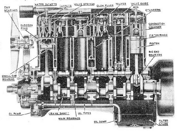
SECTIONAL VIEW showing the interior of a 130-hp high-speed Diesel engine.
Fortunately, intensive scientific investigation has led to the causes of both of these troubles being discovered. As a result, new designs of combustion chamber have more recently been evolved which entirely overcome these drawbacks. This statement will be appreciated when it is mentioned that at present there are several hundred motor-buses running through the London streets fitted with modern high-speed Diesel engines, and the public is quite unable to distinguish them from the ordinary petrol engine buses.
One seldom, if ever, experiences the exhaust or thumping noises associated with petrol engines.
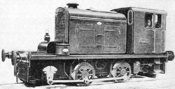
A MODERN TYPE of British Diesel Locomotive, which was built at Leeds. The engine weighs 19 tons, is of 120 h.p., and was made for the standard gauge.
Although this type of engine owes its inception to the inventive genius of an Englishman, Herbert Ackroyd-Stuart, its subsequent development by a German, Dr. Rudolf Diesel, has led to the association of the latter's name with this class of internal combustion engine.
The Diesel engine differs from the steam engine-boiler type in that it burns its fuel in a compressed air charge within the cylinder itself. In the steam locomotive the fuel is burnt much more wastefully in the firebox of a boiler to convert water into steam, the latter being admitted into the cylinder of a steam-engine working at lower pressures and temperatures.
Whatever type of engine is used, the higher the working temperatures and the average pressures in the cylinders or chambers of the engine, the greater will be the proportion of the fuel's heat available for useful work in the form of horse power. It is for this reason that modern steam engines of the reciprocating and turbine types endeavour to use high temperature - or superheated steam - and high boiler pressures. The Diesel engine is particularly efficient in this way, for it attains much higher temperatures and pressures from the combustion of its fuel than is possible with the steam engine.
The fuel used for modern Diesel engines is a moderately viscous heavy oil derived from the distillation of petroleum, known as Diesel oil. This fuel is heavier and has more “body” than either petrol or paraffin, yet will readily flow through small pipes.
The principle of the Diesel engine consists in compressing a charge of pure air to a very high pressure. This process of compression causes the air to become extremely hot; its temperature reaching 500 to 600 degrees Centigrade; these temperatures will be appreciated when it is stated that zinc melts at 419 degrees Centigrade, and aluminium at 659 degrees Centigrade. The fuel oil is sprayed into this highly-heated air, and at once ignites, causing a fairly rapid rise of temperature and pressure. The effect of this combustion is to cause the piston of the engine to be forced downwards thus exerting a powerful turning effort on the engine’s crankshaft. To understand the working of the Diesel engine more clearly, let us suppose that we have a cylinder fitted with a piston that can slide up and down. The sequence of operations will then be as follows:
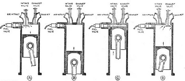
THE FOUR-CYCLE DIESEL ENGINE. (A) Air suction stroke, piston descending. (B) Air being compressed by ascending piston. (C) Fuel being sprayed into heated, compressed air, and igniting. (D) The exhaust stroke. After descending on the firing stroke, the piston again ascends, driving out exhaust products through the exhaust valve.
The piston is at the bottom of its stroke, the cylinder being filled with air previously “sucked” in from the outside atmosphere. Next, the piston is made to ascend so as to compress this air into a very small volume; in Diesel practice the air at the end of the compression stroke occupies about one-fifteenth of its initial volume. Just before the top of this compression stroke, the oil-fuel is injected under a very high pressure, namely, from about 1,500 to 2,000 lb per square inch; so that it emerges into the compressed air (which is usually at a pressure of about 500 lb per square inch) in the form of an extremely fine. spray or mist. This immediately burns with the oxygen of the air charge and in doing so causes the latter to increase in pressure and temperature.
Usually, during the combustion process the pressure rises to 800 or 1,000 lb per square inch. This high pressure forces down the piston, while the highly-heated gases, which are the products of combustion of the oil and air, experience an expansion effect which results in a downward power stroke.
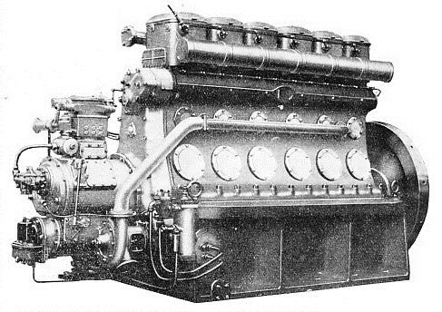
THE IMPOSING EXTERIOR of a Beardmore high-speed Diesel engine. This engine develops 320 to 360 brake-horse-power at 800 to 900 revolutions per minute.
The next upward stroke of the piston is used for clearing the burnt gases out of the cylinder through an opening known as the exhaust port. Normally this is closed by the exhaust valve, but during the gas-clearing or exhaust stroke this valve is arranged to open. When the piston gets to the top of its exhaust stroke the exhaust valve closes, but at this moment another valve opens, uncovering a passage leading direct to the open air; this is known as the air inlet valve.
As the piston moves downwards once more the suction effect created causes the air from outside to flow into the cylinder, until the latter is completely filled with air at the same pressure as that outside, namely, atmospheric. After this, while the piston is at the bottom of its stroke the inlet valve is closed by suitable mechanical means, the exhaust valve still remaining closed. We have thus arrived at a similar state to that begun with, and the air is ready for its compression stroke; the cycle of operations is now complete.
It will be seen that each consecutive working cycle of the Diesel engine is made up of four working strokes, these - in their respective orders - being (1) compression; (2) combustion and expansion; (3) exhaust, and (4) suction. Owing to the fact that four strokes, or two revolutions of the engine are necessary to complete the cycle, this type is known as the four-cycle engine.
There is only one working, or power, stroke in the four strokes that make up this cycle, the other three being non-productive.
To overcome the somewhat jerky or erratic nature of the working, it is usual to fit the engine crankshaft with a flywheel. If the engine has only one or two cylinders a larger flywheel will be necessary than for engines having four or more cylinders.
The Two-Cycle Engine
The object of the flywheel is to store some of the surplus energy from the power stroke and to give this energy out again for the three non-productive strokes. In the Diesel engine the time taken by each cycle is very short; thus the complete cycle occupies only about one-twelfth of a second in the case of an engine operating at 1,500 revolutions per minute.
There is another type of Diesel engine possessing advantages over the four-cycle one described. This is known as the two-cycle engine, from the fact that each working cycle occupies only two strokes, or one revolution of the engine. In this engine the exhaust and suction strokes, performed by the piston in the four-cycle engine, are dispensed with, so that the piston is used only for the compression and combustion-expansion strokes.

THE TWO-CYCLE DIESEL ENGINE. The cycle of operations is as follows. (D) Piston ascending, compressing air in the cylinder. (C) End of compression; fuel oil being sprayed in and igniting. (B) Expansion or firing stroke, piston descending. (A) Piston at end of firing stroke. Exhaust gases escape through port B ; fresh air charge enters cylinder through transfer port D. When ascending piston uncovers port C, suction causes air to flow into the crank chamber.
The general method of accomplishing this is to arrange for the piston when moving downwards on its expansion stroke to uncover near the bottom of its travel - a port or ports cut through the cylinder walls. When thus uncovered the expanded burnt gases can escape into the exhaust pipe. When the piston moves down still farther, and is practically at the bottom of its stroke, it next uncovers another port or set of ports, thus allowing a charge of fresh air to be forced through these ports under pressure into the cylinder. As the piston moves upwards on its next stroke, it covers the inlet and exhaust ports, and then proceeds to compress the new air charge to the same high compression pressure as in the four-cycle engine.
Near the top of this stroke fuel is injected and combustion takes place, followed by expansion of the hot combustion products during the ensuing expansion stroke: the cycle of operations is thus completed.
The fresh air charge is usually forced through the inlet port by means of a separate air compressor, and in greater quantity than is needed completely to fill the cylinder. Part of this air is therefore used for clearing out the exhaust gases remaining in the cylinder, a process known as “scavenging”. This air also serves to keep the cylinder temperatures down to reasonable values, for it must be remembered that with the two-cycle engine twice as many combustions occur as in the case of the four-cycle engine, in the same period of time. There is, therefore, approximately twice the amount of heat developed.
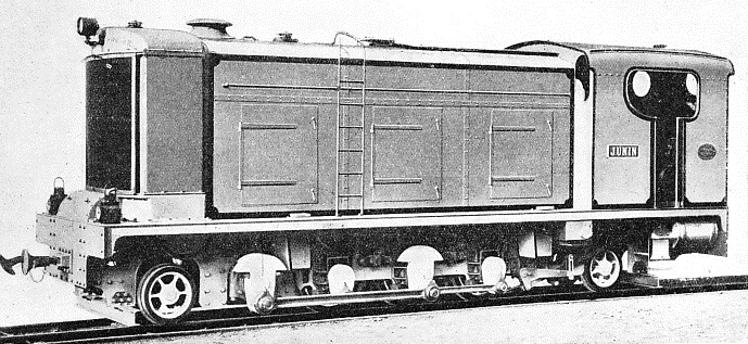
A 330-HP DIESEL LOCOMOTIVE. This British engine was built for service in Chile. It weighs 31 tons and is made for the 2 ft 6 in gauge.
The two-cycle engine, having two power strokes for every one of the four-cycle engine running at the same speed, should, theoretically, give twice the power of the latter engine. Owing, however, to various technical reasons concerned with the charging of the engine cylinders, the best high-speed two-cycle engine gives only about sixty per cent more power than the equivalent four-cycle one. With such a gain, however, it is possible in practice to make much lighter and more compact two-cycle Diesel engines than four-cycle ones. In aircraft types the two-cycle Junkers engine is about two-thirds the weight of the best four-cycle engine of similar output and speed. In the instance of large Diesel engines of the slower variety the two-cycle engine can be made to operate very efficiently, so that its output approaches more nearly double that of the four-cycle type. At present, the principal drawback of the two-cycle Diesel engine for railway work is its rather higher fuel consumption than the four-cycle type, and its shorter working life.
We have seen that it is necessary to provide a clutch and transmission system - or their equivalent-when Diesel engines are used for railway purposes. In this connexion there are three principal systems in use, as follows: (1) the clutch and gear-box; (2) the hydraulic; and (3) the electric types.
The first system is similar in principle to the transmission of the ordinary motor car. This possesses the drawbacks of giving only three or four steps in the speed variations, and in requiring a certain skill on the part of the driver in making the gear-changes. The later pre-selective gear-box, as used on the AEC rail-car, obviates the latter disadvantage.
The hydraulic transmission method is a decided advantage over the former one, since it gives a smooth continuously variable tractive effort, and does not require a clutch. Moreover, it requires very little skill on the part of the driver in making starts and speed changes.
The electrical transmission method has been used in several successful railcars. It consists in coupling the engine to a dynamo, then using the current obtained from the latter to drive electric motors placed on or near the axles of the driving wheels and, in the latter instance, connected by gearing, in order to obtain the required speed reduction. The electrical method is a particularly convenient one to employ, as it gives a continuously variable tractive effort, and affords the driver easy control.
Electrical Transmission
Another advantage lies in the fact that the losses of the system are mainly heat losses, the friction losses being at a minimum, so that there is a minimum of wear and tear, while at the same time the engine is protected against rail shocks. The question of supplying energy for the auxiliary services, such as train lighting and heating, brakes and similar items, is also readily dealt with by the electrical system mentioned; no additional equipment is therefore necessary as with other transmission systems. And there is another advantage; the Diesel engine can readily be started by using the dynamo as a motor, the current being obtained from the storage battery forming part of the electrical system.
The dynamo used for Diesel-electric drive is of special design, and has what is known as a “dropping characteristic”, so devised that the voltage automatically adjusts itself to the varying current demand from the tractive motors, while the power output remains constant over a very wide range of operation. The Beardmore Diesel-electric locomotives employ this system, one notable example being that of the engines built for the Canadian National Railways. These locomotives weigh 290 tons each and are fitted with two Diesel engines of the twelve-cylinder Vee-type of 1,330 brake-horsepower, i.e. a total of 2,660 brake-horsepower. The locomotive gives a starting tractive effort of 100,000 lb with a continuous effort of 42,000 lb. It is capable of hauling freight loads up to 4,000 tons at twenty-five miles an hour, or fast passenger trains of 1,500 tons at a speed of sixty-five miles an hour.
FOR THE RAILWAY IN INDIA. This small Diesel locomotive weighs 4½ tons, has wheels of 16 in diameter and an overall length of 10 ft 2 in. It can haul a load of approximately 105 tons on the level.
Another interesting transmission system is that used in the Associated Equipment Company’s original railcar. The latter is fitted with a 130 horse power high-speed AEC Diesel engine of the six-cylinder type, similar to that used on a large number of London’s omnibuses. The power is transmitted from the engine to a kind of hydraulic clutch, known as a “fluid flywheel”.
The latter consists of an outer aluminium casing secured to the engine crankshaft, and an inner “paddle wheel” unit secured to the gear-box mainshaft. There are a number of cup-shaped cavities inside both members, the space between the two units being filled with a fluid. The engine casing drives the “paddle wheel” by means of the fluid, but it will drive the latter only under ordinary loads, when the engine speed exceeds 500-600 revolutions per minute.
The gear-box used in the AEC railcar is of the Wilson pre-selective type fitted to some motor-cars. The driver makes shock-free gear changes with the combination of fluid flywheel and pre-selective gearbox.
You can read more on “British Diesel Rail Coaches”, “Diesel Shunting Locomotives” and
“The Flying Hamburger” on this website.


 a total of 2,660 brake-