
© Railway Wonders of the World 2012-


The Simplon Tunnel
Driving a Railway Through the Alpine Barrier
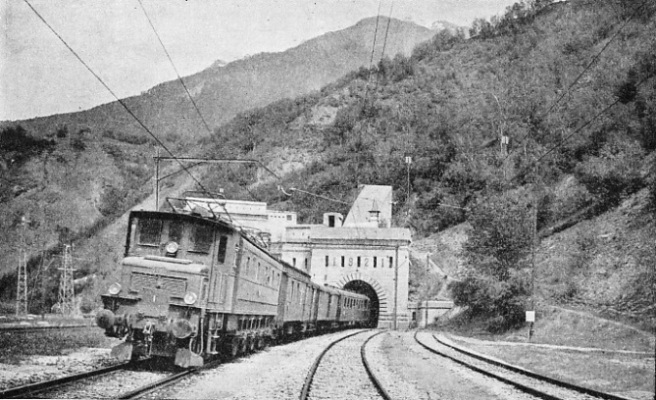
THE NORTH PORTAL of the Simplon as seen after the completion of the second tunnel in 1921. The double tunnel, the longest in the world -
IN ancient times and in the Middle Ages the Simplon Pass was merely a narrow path, but its importance as a means of communication between France and Italy was considerable. Some vestiges have remained to testify of its use in Roman times, and from old chronicles of the thirteenth and fourteenth centuries we learn of the existence on the Simplon of a hospice, which still exists. But the road, if such it could be called, was far from adequate, nor was it suitable to carry heavy traffic.
The Emperor Napoleon was the first to visualize the importance of the Simplon as one of Europe’s highways. He included the passage over the Simplon in his plans for the Italian campaign. In 1801, a year after the battle of Marengo, the construction of this great military road was begun. On its completion, four and a half years later, it had a length of thirty-
The first serious project for the construction of a railway tunnel under the Simplon Pass dates from 1857, ten years after the completion of the first railway in Switzerland from Zurich to Baden.
Several other plans were submitted from time to time by various syndicates formed for the purpose, and some of them by the then privately owned Swiss Railways. Among these projects was one for the construction over the Simplon of a rack railway on the Fell System, while another envisaged the construction of inclined planes with cable railways. In all, some thirty plans were submitted. As far back as 1889 the Swiss Government had invited the Italian Government to a conference at Berne, at which the basis for joint action was laid down.
The Italian delegates insisted that the greater part of the tunnel should be laid on Italian territory and, in company with the representatives of the Swiss Federal Government, pressed for the submission of a concrete project. In 1890 a new conference was held, in which the famous firm of Gebruder Sulzer, of Winterthur, took a leading part, together with the contractors Brandt and Brandau. The project was examined by a special commission appointed by the Swiss Government, and composed of three civil engineers of European reputation, Sir Francis Fox, Professor G. Colombo of Milan, and Herr C. J. Wagner, Chief Engineer of the Austrian State Railways. The commission approved the project, both from a technical and from a financial standpoint. The estimated cost of construction was 69,500,000 francs (£2,780,000 gold).
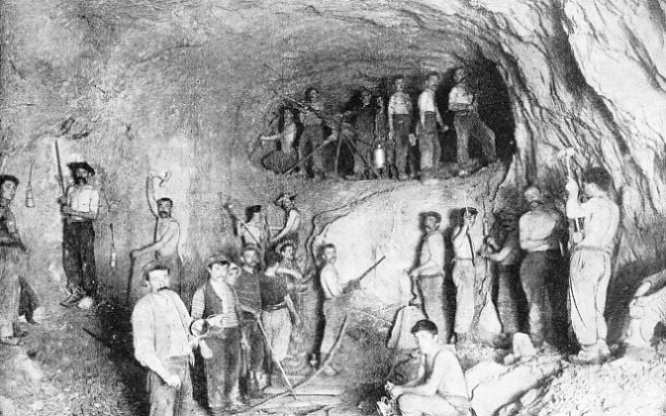
AT WORK ON THE TUNNEL HEADING. Brandt hydraulic drills were used during the construction of the Simplon Tunnel. The machines were equipped with four drills capable of driving holes from 4 to 5-
In the meantime the negotiations between the Swiss and Italian Governments had come to a satisfactory end by the conclusion of the Simplon Agreement of November, 1895, in Berne. Simultaneously the Jura-
It is as well to bear in mind that the construction of the tunnel was begun in 1898. It is perhaps difficult for the younger generation to appreciate the fact that civil and mechanical engineering had not then reached the advanced stage of progress which it enjoys to-
Such were the conditions in which the construction of the tunnel had to proceed.
An Original Method
It was indeed a gigantic enterprise to bore through the mountain mass of the Alps, below snow-
The experience gained in the construction of the St. Gothard Tunnel enabled the engineers to adopt an original method of construction, which included the boring of a secondary tunnel, parallel to the main one, of smaller section, and for the time being destined to fulfil the function of a service and ventilation tunnel. It was intended to widen the service tunnel to the normal section at a later date when traffic requirements should justify its use as a second railway tunnel. One condition of the contract was that the official request for the completion of the second tunnel should be made within four years of the completion of the first tunnel.
In accordance with the original specifications the main tunnel had a section of 14 ft 9 in by 18 ft ½ in, while the service tunnel had a section of 10 ft 6 in by 8 ft ½ in. The principal purpose of the service tunnel was to accommodate the water-
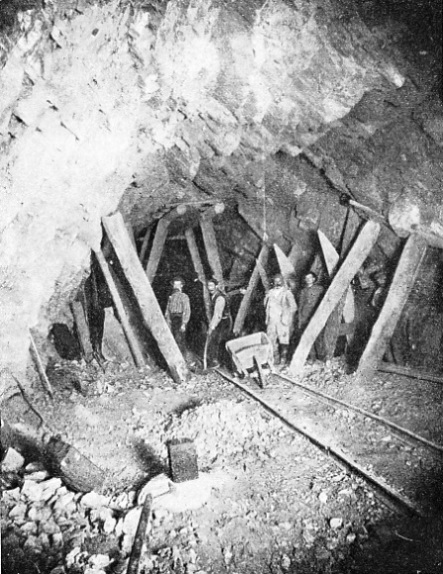
ENLARGING THE FIRST GALLERY. The main tunnel had to be constructed with a section 14 ft 9 in by 18 ft ½in, and the service tunnel with a section 10 ft 6 in by 8 ft ½-
Exhaustive geological surveys had been carried out to establish as closely as possible the nature of the soil to be traversed. But, as geological science in those days had not reached its present state of advancement, the theoretical forecasts of the geologists were not always borne out by facts. In some instances this turned out to the advantage of the contractors, as, for example, when the supposed extent of hard rock came to an end much earlier than had been expected. In other instances, the sudden appearance of water indicated the premature presence of lime.
One noteworthy instance of inaccurate forecasting deserves mention. According to the geologists the soil at the southern side of the tunnel was formed of compact hard gneiss over a distance of four and a half miles, and it was succeeded by lime formation and calcareous schists. In reality, the gneiss was in layer formation for over two and and a half miles, and was followed much earlier than expected by calcareous schists, which caused tremendous pressures.
The lessons learned during the construction of the St. Gothard Tunnel, where over 800 men died from illness, had not been forgotten by the contractors; every possible precaution was taken by them to ensure the material and moral welfare of the thousands of men engaged upon the construction of the Simplon Tunnel. On the Swiss side an entire village was built at Naters near Brig, while on the Italian side a similar village was laid out at Balmalunesca.
Large halls, divided into small cubicles, each containing a shower-
At either entrance large yards were laid out which contained the machinery hall, with smithy and repair shops, cement and brick works, timber yards, stores, stables, depots for explosives, and so forth. The yard at the north entrance covered an area of 195,000 sq ft, that at the south entrance an area of 98,000 sq ft.
For the purpose of ensuring a permanent water supply, special aqueducts were constructed on either side. On the north side the water was derived from the River Rhone, and conveyed by a reinforced concrete canal, two miles long, to a place called Massaboden, where the water entered the pipe-
On the southern side similar arrangements were made. The water was taken from the River Diveria, and conveyed through a pipe-
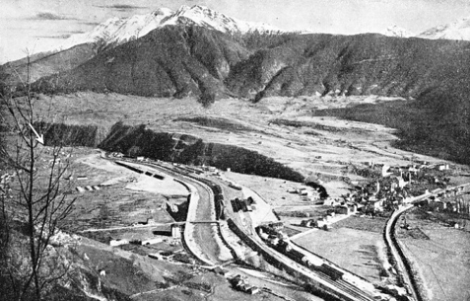
THE FORMIDABLE MOUNTAIN BARRIER through which the Simplon Tunnel had to be driven can be seen from this remarkable picture. The arrow on the left of the illustration denotes the northern entrance of the Simplon Tunnel. In the foreground is the station of Brig.
The drills were mounted on a 12-
One machine was provided with four drills, and was capable of driving, in different directions, four holes of from 4 to 5-
Four Great Obstacles
They had to be changed continuously, often as much as 300-
Progress of the work was considerably delayed by unforeseen factors, which at last endangered matters to such an extent that operations had to be suspended at a certain point, and it seemed as if the completion of the tunnel would have to be abandoned. The four great obstacles were high temperatures, pressure of the soil, inundations, and hot springs.
From the experience gained during the construction of the St. Gothard Tunnel, the geological nature of which appeared similar to that of the Simplon, it was thought that the maximum temperature encountered would be 107° F. In reality it reached on the Italian side 115° and on the Swiss side over 129° F. Special provisions had therefore to be made to render the temperatures endurable, although the contractors were unable to keep the temperature down to the 77° stipulated in the contract. The ventilation air conveyed through the service tunnel was not sufficient to reduce the temperature, and it became necessary to lay within the service tunnel a pipe-
The pipe-
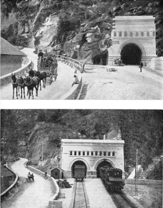
THE SIMPLON TUNNEL YESTERDAY. This interesting illustration shows the southern entrance as it appeared shortly before completion in 1906. Beside the main portal can be seen the service tunnel, later widened and converted to a second tunnel. On the left is the famous Simplon road, with a fast coach of the type used to carry the mails before the tunnel came into use.
THE SIMPLON TUNNEL TO-
An unusually heavy pressure of soil was encountered on the Italian side, where, at point 4422, a pocket of micaceous lime schist was met. This is about the worst kind of soil imaginable, its consistency being that of a soft clay, which exerts pressure in all directions. The usual method of drilling and blasting could not be adopted, as the material was too soft. The pocket had, therefore, to be attacked by hand and immediately shored up. But the wooden supports were not strong enough to resist the enormous pressure and broke in pieces. The strongest oak beams, with a section of 20 in by 20 in were distorted, although their height was only 6½ ft.
After various experiments, a system was successfully adopted which consisted in the use of iron frames constructed of channel girders 16 in deep, 6⅛ in wide across the flange, and ⅝-
The construction of this length of tunnel is particularly interesting because of the unusual method adopted. After the rectangular iron framework described above had been placed in position over the whole length, it formed a rectangular tube. To excavate this to the full section of the tunnel, side shafts were excavated over short distances on one side of the uprights and immediately lined with strong oak props. Then the same was done on , the other side. In this way it was possible to get at the soil immediately below the bottom horizontal iron girder of the framework. This soil was excavated, and the centre part corresponding to the horizontal girder was completed with strong masonry work, which was continued on either side until it reached the level of the bottom girder.
 The thickness of this inverted arch varied from 8 ft 2½ in to 9 ft 2 in. After completion of the inverted arch the section at the sides of the iron uprights was excavated and the masonry work was completed, beginning from the outer edges as far as the springing of the arch.
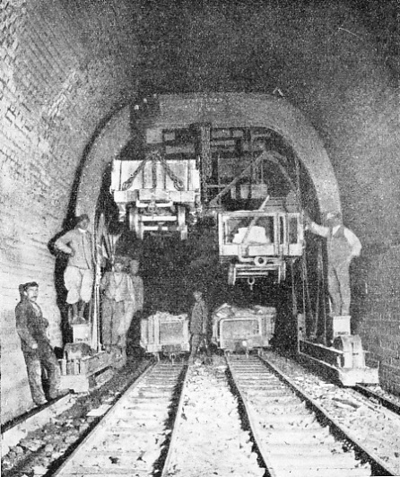
DURING THE CONSTRUCTION of the second tunnel special overhead travelling cranes were used to transport the excavated rock from the narrow-
The whole work was done simultaneously at various points at a suitable distance from one another. This work required a whole year, and progress was delayed also through the continuous stoppages of work due to the many service trains which passed through the iron tunnel. The completion of this length took another six months, so that in all over two years were required for the construction of 138 ft of tunnel.
Delays were caused also by the enormous quantities of water encountered. During the late summer of 1900 a fall of temperature in the heading from 91° to 79° had been observed between points 2400 and 3800, distant respectively 2624 and 4156 yards from the south portal. It was not till May, 1901, that the explanation of this phenomenon was given. At point 3824 the advance heading encountered a heavy influx of water, which rushed through the bore-
It was found that the tunnel had been bored 2,000 ft below the surface of an immense reservoir of water. At point 3891 the roof of the advance heading split under the pressure of water, which poured in at the rate of 2,500 gallons per minute. Fortunately this huge quantity diminished later until it reached twenty gallons per minute.
At point 4364 another inundation occurred, this time in the service tunnel. The amount of water was 3,000 gallons a minute. The worst influx of water occurred at point 4397. It became necessary to block the heading with sandbags, so as to form a reservoir to oppose the onrush of water. This method was successful, and permitted the boring of a. by-
Hot springs encountered on either slope of the tunnel caused serious and repeated stoppages. The temperature of these hot springs varied between 113° and 122°F, and work became impossible because of the hot air in the headings, which rose to 104°.
The hot springs met with on the southern slope at point 4500 were particularly serious. The heading was flooded over a length of 900 yards, and, to proceed with the work, a cross-
The air -
Menace of Hot Springs
On the northern side matters were still more difficult, as the tunnel was bored on an up gradient, the highest point of which was at point 9594. From here to the south portal the tunnel was laid on a down gradient of 1 in 145. During the work on the down gradient the waters had to be pumped up to the culminating point, as there was as yet no natural outlet available to the south. Matters proceeded satisfactorily up to point 10150, where hot-
Shortly beyond this, at point 10378, a new inrush of hot water occurred, at the rate of 500 gallons a minute. Unfortunately, the machinery plants on the northern slope came to a standstill because of a mountain slide above the intake of the power station, which was put out of function. Pumping and ventilating machinery driven by the current produced there became idle, and the whole work on the northern side had to be abandoned. Powerful steel doors set into heavy masonry were erected near the cross gallery which connected the main tunnel with the service tunnel, and the water accumulated in the tract between the advance headings in both tunnels and the two steel doors.
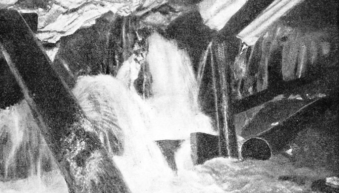
AN INUNDATION of the tunnel workings caused by the incursion of some cold springs. At one point water poured in at 3,000 gallons a minute and threatened the enterprise. A by-
The boring of the tunnel was continued from the south side only, and on February 24, 1905, the last cartridge was exploded, and the hot water rushed from the northern side through the opening. Communication was thus established after 2,392 working days. The average progress had therefore been over 27 ft per day. The completion of the tunnel required almost a year, and the official opening was on January 25, 1906. The world’s longest tunnel, and one of the world’s greatest pieces of civil engineering, was completed, a lasting tribute to Swiss engineering.
As mentioned above, the Jura-
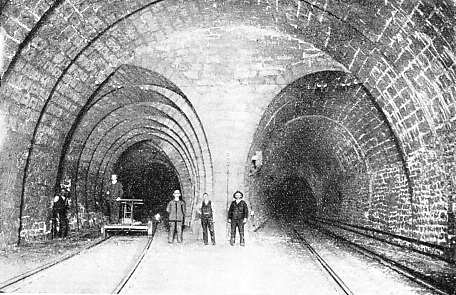
THE FIRST TUNNEL contained a station about half-
A Commission set up by the Administration of the Federal Railways concluded in its report that the systematic completion of the service tunnel was unavoidable, but that it would be advisable to proceed at once with the widening of the service tunnel instead of undertaking merely its completion. Sooner or later, the second tunnel would be required for traffic. The Federal Railways therefore called on Messrs. Brandt, the contractors, to build the second tunnel on the same scale as the first.
In view of the altered conditions the firm obtained release from its contract, and the Swiss Federal Railways undertook the work themselves. They created for the purpose a special construction department, on which devolved the responsibility for the safety of the first and the completion of the second tunnel.
Before the work could be begun it was necessary to put the plant of the late contractors, Messrs. Brandt, into working order and to modernize it. Since the first tunnel was started, engineering had made great progress. New and more economical machines were available which made the scrapping of old ones imperative. Nearly all the boring and drilling plants were replaced by pneumatic tools, new at that time, which were capable of six to ten times as much work as the hydraulic Brandt machines.
The transport of the excavated material from the advance headings of the first tunnel had been effected with compressed-
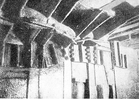
TREMENDOUS PRESSURE. The deformation of the steel lining of the Simplon Tunnel through the tremendous pressure of wet soil is clearly shown in this picture of a section of the roof.
The old machinery hall was retained and equipped with some modern machine tools, and new carpenter shops were erected. Electric power was supplied by the electricity supply companies at Brig and Iselle respectively, and special transformer stations of 1,600 kVA and 1,800 kVA respectively were erected to step-
Special provisions tor the removal of the excavated material had to be made on the northern entrance, where it would have been impossible to allow the narrow-
The war of 1914-
You can read more on “The Channel Tunnel”, “The Great Apennine Tunnel” and “Tunnelling Against Time” on this website.
You can read more on “Alpine Tunnels” and “The British Empire’s Longest Tunnel” in Wonders of World Engineering