A Generating Station for the Supply of Electricity
UNDERGROUND RAILWAYS - 6

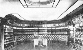
THE CONTROL ROOM at Lots Road Power Station, Chelsea, which was opened in February, 1905. The power station supplies electricity to the District Railway, the Central London, City and South London, and London Electric Railways, East London Railway, the Whitechapel and Bow Railway, and sections of the Southern Railway, also to the London United Tramways. The illustration shows a view of the many control panels.
FOR more than thirty years Lots Road Power Station has been one of the most important buildings in London. Its four tall chimney-stacks - the tops of which are 275 ft above the ground - have made it a landmark familiar to most Londoners. Nowadays, there are newer and more powerful plants for generating electricity in the straggling area known as London; but whenever the phrase “power station” is mentioned, nearly all Londoners connect it instinctively with the building in Lots Road, Chelsea, which, year in and year out, has efficiently supplied the electricity for their transport.
From 1905, when this power station began operating, electricity has never for a moment ceased to flow from it, both night and day. Even in the small hours, when most of the Tubes and other electric railways of the London Passenger Transport Board are closed to the public, the power station is still sending out current for various purposes.
In the design, equipment and operation of a modern electric power station there are problems for the engineer’s solving, not only of a mechanical nature, but also relating to economics - or, in other words, cost in money. Among such problems is that of peak-loads. By this is meant the amount of electrical energy demanded of the power station during the “busiest” period of the twenty-four hours. The generators must be numerous and large enough to supply the demands of all consumers during the peak period. There is no question of a partial supply, as the current pressure (volts) and its volume (amperes) have to be maintained.
Electrical generators are expensive machines to build, install and maintain, so that, unless they are in full use every hour of the twenty-four, there are periods when they will be lying idle without “earning their keep”. Full-time service is, however, impracticable. It is in his compromise with the joint demands of economy and of the consumer that the power station engineer deals with one of the most difficult problems submitted to him.
The Lots Road plant, with its primary function of supplying power to London’s electric railways, has its “peak” periods at nine in the morning and again at six in the evening on five days of the week - from Monday to Friday inclusive. On Saturdays the six o’clock peak is transferred to one o’clock. These periods coincide, of course, with the traffic “rush hours”, with greatly augmented train services cope with the press of City workers travelling to or from their employment. The output of the power station is recorded by means of charts on squared paper. One side or margin denotes the time in hours and minutes; the other shows the load in kilowatts. A kilowatt is the standard unit of measurement for electric power, and is equivalent to 1,000 watts. A watt is one volt multiplied by one ampere. The kilowatt of the electrician is analogous to the horse-power of the steam or motor-car engineer. In fact, one kilowatt is equivalent to 1-1/3 hp.
Lines on the chart from the “time” and “output” sides respectively meet at right-angles, and the points of intersection, when joined together, form a graph, showing at a glance the load on the station at any minute of the day or night.
On a weekday the graph will show two “mountain peaks” at nine and six o’clock coinciding with the rush hours, with “valleys” between, when the flow of traffic has lessened.
Big events in London are reflected in these graphs. Thus, the graph for Jubilee Monday, 1935, shows that the load curve rose sharply between 5.30 and 6.30 in the morning - when thousands of people were travelling by Underground to get to their places, on the route of the Royal procession - and kept practically level for the rest of the day. As factories and offices were closed, there was no rush hour to send it up to its usual peak.
Another curve which indicates a piece of history is that for November 29, 1934. This was the wedding-day of the Duke of Kent and Princess Marina, which had the effect of filling the usual “valley” between the rush hour peaks.
1,200,000 Kilowatt Hours
Lots Road Power Station may be described as a huge machine into which coal enters at one end to emerge as electricity at the other. On an average day, 750 tons of coal enter the power station dock. This amount is converted in the power station to about 1,200,000 kilowatt hours, and is distributed to thirty-five railway sub-stations and ten tramway sub-stations by more than 460 miles of 11,000-volt high-tension three-core cable.
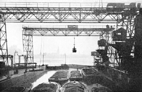
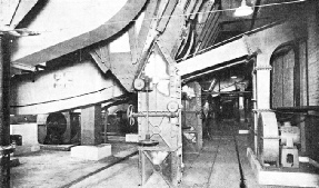
The coal arrives in lighters, which are brought into the basin when the dock gates are opened round about high water. The capacity of the dock is such that six lighters, each carrying up to 200 tons of coal, can be berthed under two transporter cranes. The grabs of the cranes unload the coal, which is then weighed and passed on to an endless belt conveyor that carries it to the elevator house. Here it is crushed, if necessary, and then lifted to the top of the building, to be stored in the bunkers over the boilers.
About 10,000 tons of coal are stored in a large circular tank on the river side, as a reserve in the event of an emergency that might arise to stop barges being worked into the dock.

AN AVERAGE LOAD of 750 tons of coal enters the dock at Lots Road Power Station every day. Coal is brought in lighters, each capable of holding 200 tons, which are berthed in the dock below two two transporter cranes for the purpose of unloading.
Water from the Thames is used for cooling purposes. It is drawn from the river by two pipes - one of which is 9 ft in diameter, the other being 7 ft 9 in - and is passed through revolving screens which remove most of the floating matter. It is also chlorinated to destroy the living organisms which, if left alive, would grow and clog the pipes. When the station is on peak load 7,200,000 gallons of cooling water are used every hour. When the water has been used it is returned to the Thames; it is discharged into a creek and then flows back into the river. An ash sluice passes under the building to the ash plant. The boiler-house is on the first floor, and the ash from the burnt coal falls into the ash sluice under the building, and is carried by a flow of water which discharges it into the ash sump. This is 35 ft deep and 36 ft in diameter, and is situated in the west yard. A telpher crane grabs into the sump and raises the ash to the top of the ash house. From here the ash is dropped into a hopper and fed by gravity into two rotating screens, which sort the ash into four grades of fineness, the graded ash being stored in the lower hoppers. From these hoppers it is loaded into lorries and taken away. If necessary, the ash can be lifted from the sump into lighters, which can be towed out of the creek and taken away by water. The ash is used for various purposes; some of it may form what is known as a cinder track at a sports ground, or it may be used for house building purposes. The ash amounts to about ten per cent of the coal consumed, some 75 tons being dealt with in the course of a day.
River water is not, of course, used in the boilers. Most of the boiler water is obtained from an artesian well, which goes to a depth of 500 ft. Some 12,000,000 lb of water are turned into steam every day. The bulk of this is in continual circulation, and is re-condensed into feed water in the condensers. The water which is added to compensate for leakages is drawn mostly from the well.
The nine feed pumps, which are on the ground floor of the building, are each able to deliver 40,000 gallons per hour against a pressure of 400 lb per sq in. Three of the pumps are driven by steam and six by electricity. Two air compressors, which supply compressed air to various parts of the station for tools, cleaning apparatus, and other purposes, are also housed in the pump-room.
The Condensing Plant
The condensing plant and the auxiliary gear of the turbines are housed in the turbine house basement. The condensing water from the river passes through the twin shells of the condensers. The two shells have a total cooling area of 25,500 sq ft, made up of the outer surface of 1-in special brass tubing, there being over 10,000 of these tubes. The circulating water is pushed through the tubes by pumps driven by electric motors, which are of 500 hp and are the largest motors used in the station.
The starting switches and the meters for the motors are mounted on panels, the main switches being in a room extending the length of the station on the north side of the building. The controls and switchgear for the smaller motors are arranged in the same manner. Among these smaller motors are those for extracting and returning to the boiler feed-pumps the water that has been re-condensed from the steam and has fulfilled its purpose of driving the turbines.
The boiler house is on the main floor level, and is remarkable for its coolness and the absence of stokers, the boilers being fired by mechanical means. The coal, having been passed by means of conveyors into the bunkers above the boilers, is fed down pipes by gravity into the coal hopper in front of the boiler, and is carried into the furnace by a revolving chain-grate stoker.

ABOUT 12,000,000 LB OF WATER are converted to steam daily in the boiler house - seen above - at Lots Road Power Station. Most of the boiler water is obtained from an artesian well which goes to a depth of 500 ft. The boiler are mechanically fired. On the left of the picture are the forced draught fans, in the centre, ash shoots, and, to the right, secondary air fans.
A fan driven by a 38 hp motor forces the air used in combustion through the grate, secondary air being introduced into the combustion chamber by a 14 hp booster fan motor. A glance into a furnace shows a white cascade of flame. The products of combustion are removed by an induced draught fan driven by a 96 hp motor. The gases pass through a dust extractor of the cyclone type, and so through the chimney stacks to the air.
Steam is developed at a pressure of 295 lb per sq in, and at a temperature of 750° F.
Each boiler has 6,470 sq ft of heating area, and is composed of 4-in water tubes. After the water has been turned into steam, it passes through the furnace again in the smaller tubes of the superheater, these tubes having a further 1,430 sq. ft. of heating surface. The gases, after leaving the boiler, have further heat extracted from them by more tubes containing the feed water; these tubes, which form what is called the economiser, provide 6,788 sq ft of heating surface.
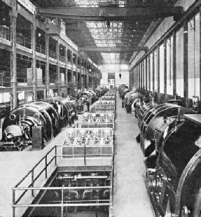
In the turbine-room the turbo-alternators are arranged in two long rows the length of the long room. Each machine consists of a high-pressure turbine cylinder on the right-hand end with the valve and governing gear. From here the steam passes to the centre of the right-hand middle part, which is the low-pressure turbine cylinder divided into two parts, the steam passing to the involutes at the outside ends and down to the condensers. The left-hand middle part is the generator, where the mechanical energy is transformed into electrical energy. On the extreme left hand is the exciter, which regulates the pressure at which the energy is turned out.
The most recent type of turbine has a capacity of 18,750 kilowatts, this being about three times as powerful as the original units of 6,000 kilowatts, but occupying very little more ground space. When the original units were installed they were the most powerful in Great Britain, but electricity has made great progress since those days.
The control-room is placed above the end of the turbine-room, and a bay window affords a complete view of the plant. Opposite the window are the panels from which the turbo-alternators are operated.
In the centre of each panel is the telegraph apparatus for signalling to the driver; below, on the right, is a hand-wheel by which the speed can be varied, and on the left is a hand-wheel which regulates the voltage. In the middle, between the two hand-wheels, is a switch, by means of which the unit can be connected to the bus bars to give its energy up to the outgoing electrical feeder cables. At the top of each panel are the instruments registering the amount of energy each unit is developing.

A GENERAL VIEW of the Generator Room at Lots Road Power Station. The maximum load of the power station is just over 100,000 kilowatts, or the equivalent of 134,000 horse-power.
The controls for the outgoing feeder cables are arranged in a semi-circle at the farther end of the control-room, each vertical unit representing one cable. At the top is the ammeter to register the load, and below this is the name of the substation being supplied. Under this are the number, the alarm indicator, the oil circuit breaker control switch with its pilot lamps - red to show the switch closed and green to show it open - and below again, relays and fuses to protect against faults and defects.
In the middle of the semicircle of feeder controls is a telephone exchange, which enables the operator to get into communication with any part of London to which a supply of electricity is being sent.
On the right of the control-room are the low-voltage, direct-current control panels, which supply the more important auxiliary plant of the station. On the left are the main metering panels of the generators, where the total output is measured.
Although the Lots Road Power Station is not the only source of power of the underground railways of London, it is the chief supply, the maximum load being just over 100,000 kilowatts, which is the equivalent of 134,000 hp.
You can read more on
“The Growth of London’s Transport”,
“The Post Office Railway” and
“Railways Under London”
on this website.


