Water troughs on British Railways
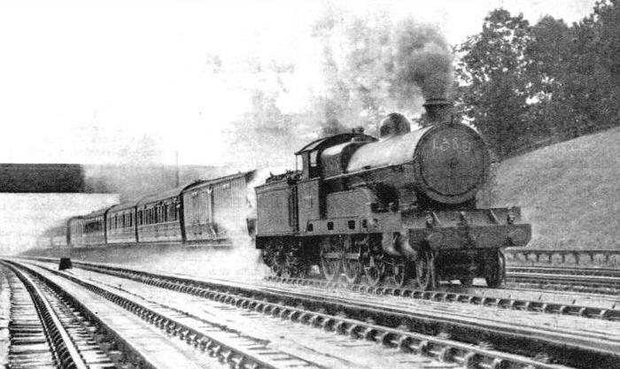
TAKING UP WATER from Bushey troughs, nearly sixteen miles from Euston, on the main line of the Western Division.
THE announcement that the London, Midland and Scottish Railway are about to lay down additional water troughs on their two Anglo-Scottish routes served as a reminder of the useful part played by these appliances in modern railway working.
It was in 1860 that Mr. John Ramsbottom, at that time chief mechanical engineer of the London and North Western Railway, introduced the water trough and pick-up system. Twenty-five years passed before any other railway company adopted them, and then the Lancashire and Yorkshire Railway put down the first of several installations. Since then practically all the main routes in the country have been equipped, enabling engines to make long non-stop runs, and also reducing the work to be done at the terminus or next stopping place.
The troughs are always laid on a level portion of the line and generally on a straight portion. The well-known troughs at Bushey, near Watford, however, are on a curve. In this special situation the troughs are so supported that the cant on the rails is neutralised, but the troughs are a little deeper than usual on account of the engine and its scoop being inclined to the horizontal. Traffic considerations chiefly decide where the troughs are to be laid, but a site is always chosen where there is an ample supply of water of a suitable quality for boiler purpose.
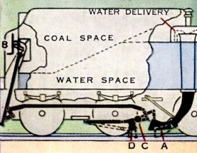
TO AVOID CARRYING large quantities of water, requiring large engine tenders or tanks, for long non-stop runs, some railways have water troughs fitted between the running rails at certain points. A scoop lowered below the engine tender may draw a fresh supply of water from these troughs as the engine passes. Travelling at speed, about 2,500 gallons of water can be picked up in a few seconds. On the diagram, which illustrates a typical arrangement for water pick up, the water scoop A) is controlled by the handwheel (B), and its weight is balanced by the counterweight C). The anti-splash plate (D) also lowers automatically with the water scoop, thus saving wastage of water.
The total length of the troughs varies, but it is usually about 500 yards, the ends gradually tapering out. Towards the end of the troughs the track is graded at 1 in 300, down at the entering end, and up at the leaving end, while the end portions have a gradient of 1 in 192. The rails are parallel to the surface of the bottom of the trough, so that if the fireman does not raise the scoop in time, it comes out of the water automatically.
The operation of picking-up water at speed splashes a good deal of water over everything in the neighbourhood, and special measures have to be taken to drain the permanent way at these places. Extra large ballast is used, with cross and side drains, and to give extra solidity to the track an extra two or three sleepers are put into each 45 ft rail length.
The troughs consist of steel plate bent to the required shape, supplied in lengths and riveted together. They are about
1 ft 6-in in width and 6-in in depth, and are placed on the middle of the sleepers and supported at the sides upon baulks of timber, cut to shape. The rim of the trough stands 3-in above the level of the rails, and the water surface is at 2-in above rail level. When the scoop is down it dips 2-in into the water, being thus at rail level and, therefore, well clear of the trough bottom and any possible obstacles.
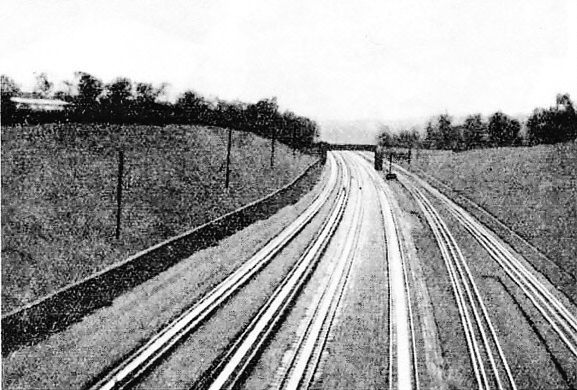
THE LMS TROUGHS at Bushey.
Arrangements have to be made to keep the troughs full of water automatically, and as this must be done fairly rapidly, the water is fed to the troughs at several points, the flow being governed by float valves similar to the domestic ball cock in the cistern. The troughs require frequent cleaning out as small pieces of ballast get washed into them and also leaves and other small pieces of rubbish.
The apparatus required on the engine is quite simple in construction. There is a gun-metal scoop, which has a thin steel cutting edge, easily renewable and adjustable for wear and tear and for settlement of the engine due to spring weakening and tyre wear. The scoop is hinged to the lower end of an iron pipe that passes up through the tender, and is jointed to the vertical delivery pipe, which has a half-round bend at the top for discharging the water into the tank. In order to allow excess water to escape, there is a hinged lid above the box covering the delivery pipe, and this opens when the tank is full. This is very necessary, as the water enters at high speed and sets up great pressure. Some tenders are provided with a pipe that discharges excess water back into the trough.
Owing to the pressure set up by the water, it is not easy to raise the scoop when the engine is travelling fast, and it may be necessary to raise it before the end of the. trough is reached. This is usually done nowadays by a small cylinder and piston, actuated by steam, compressed air or vacuum. A balance-weight keeps the scoop normally up, the cylinder being employed to push it down. On tank locomotives, which may run either chimney or bunker first, two scoops are required. They may be separate fittings, or made to lower together. In the latter arrangement one of the scoops simply trails idly in the water while the other is picking up. A hinged flap in the vertical pipe prevents the water escaping by way of the idle scoop.
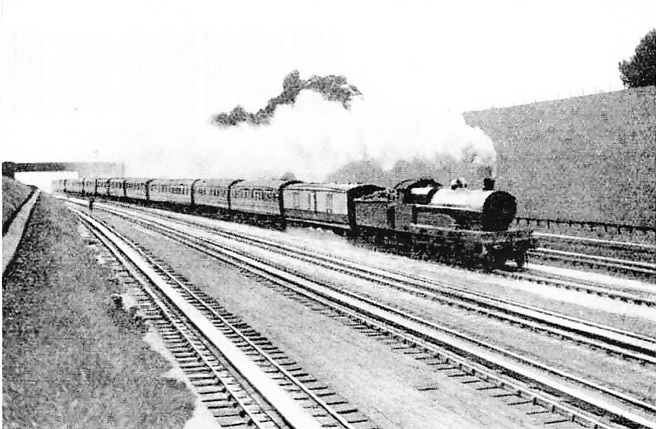
LMS DOWN 11.10 a.m. non-stop at Bushey. Engine “Rupert Guiness” No. 668.
The lowest speed for the locomotive at which the water will rise high enough in the delivery pipe to discharge into the tender tank is about 15 to 20 miles per hour, and the higher the speed the more water can be picked up. When a train has two engines drawing it, the leading or pilot engine dips in first, and about half-way along the trough the train engine dips in and the pilot takes out his scoop. Many of the late Midland Railway engines, on account of the extensive piloting resorted to on that line, had steel shields fitted in front of the leading wheels to prevent small stones being thrown up into the motion by the water-splash created by the pilot engine. This refinement is not in general use however.
In order that readers may be able to look out for these troughs whenever they are travelling, we give below a list of all those on the British railways. They are invariably laid in both the up and the down lines.
LNER
Between Lucker and Belford; between Northallerton and Danby Wiske; near Charwelton and Killamarsh stations; between Bentley and Ipswich; between Burston and Tivetshall; at Langley; between Knebworth and Stevenage; at Werrington Junction, N. of Peterborough; between Newark and Carlton, N. Of the Trent; between Scrooby and Bawtry; at Hatch End, between Pinner and Bushey.
LMS
Between the following places:- Wolverton and Castlethorpe; Rugby and Brinklow; Rugby and Brandon and Wolston; Tamworth and Lichfield; Whitmore and Madeley; Preston Brook and Moore; Brock and Garstang; Hest Bank and Bolton-le-Sands; Low Gill and Tebay; Waverton and Chester; Connah’s Quay and Flint; Prestatyn and Rhyl; Llanfairfechan and Aber; Diggle and Marsden; Eccles and Weaste; Halebank and Ditton; Horbury Junction and Wakefield; Hoscar and Burscough Bridge; Kirkby and Fazakerley; Lea Road and Salwick; Lostock Junction and Bolton; Rufford and Burscough Junction; Rochdale and Smithy Bridge; Sowerby Bridge and Luddendenfoot; Moorside and Wardley and Walkden; Knottingley and Whitley Bridge; Oakley and Sharnbrook; Loughborough and Hathern; at Melton Mowbray; at Tamworth; at Hawes Junction.
GWR
Near Goring; near Keynsham, between Bath and Bristol; near Creech, between Bridgwater and Taunton; at Exminster; near King’s Sutton, between Oxford and Banbury; near Lapworth, between Warwick and Birmingham; between Charlbury and Ascott-under-Wychwood; between Aldermaston and Midgham; at Westbury; at Chipping Sodbury; near Severn Tunnel Junction; between Ferryside and Carmarthen; near Ludlow; at Denham.
There are no water troughs on the Southern Railway or on the Irish railways.
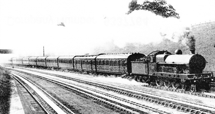
THIRD PART OF THE LMS 10 a.m. Scotch Express (4-6-0 Loco No. 2427) at Bushey.
You can read more on “Locomotive Accessories”, “Seen From the Train” and “Signals and Signalling” on this website.


