The Principles of the Joy and Walschaerts Motions
DESIGN AND INVENTION - 13
THE Stephenson, Allan, and Gooch link motions required four eccentrics on the driving axle, as explained in the chapter “Locomotive Valve Gears”. With inside-cylinder engines this requirement restricted the thickness of the crank webs - a serious matter as the engines increased in size. The grades of steel used in modern crank axles were formerly unknown, and breakages of crank axles in service led locomotive engineers to seek other positions for the eccentrics, or else to do away with them altogether. A number of engines were built with steam-chests outside the cylinders, and the eccentrics were placed outside the wheels; others had inside valves as usual, but outside eccentrics, connexion being made by rocking levers.
Joy’s Valve Gear
In 1879 the late David Joy, who at one time was Locomotive Superintendent the old Oxford, Worcester and Wolverhampton Railway (known among the railwaymen as the “Old Worse and Worse”, and now part of the Great Western Railway), invented a valve gear which abolished eccentrics entirely, and left the crank axle free, so that substantial crank webs could be fitted, and a centre bearing also provided if necessary. This valve gear was especially adapted for locomotives with valves above or below the cylinders; it was tried on an old Bury type goods engine on the Furness Railway and proved, successful. In June 1880 the London and North Western Railway fitted it to a new 0-6-0 goods engine, after which it was extensively adopted. It has continued in use down to the present day, although it is not now fitted to new engines.
Joy’s valve gear is very simple. A radius rod connects the valve spindle to a pair of die-blocks which slide up and down curved guides attached to a shaft, known as the “slide shaft” or “reversing shaft”. If these curved guides are vertical, so that the top and bottom of them are equidistant from the valve spindle, the radius rod can be moved up and down by the motion of the die-blocks; yet the valve spindle will not move. This is the mid-gear position. The end of the slide shaft is provided with an arm by which it is operated from the cab, connexion being made, by the usual reach rod, to the hand lever or wheel-and-screw on the footplate.
If the slide shaft is tilted forward, it is obvious that when the die-blocks are at the top of the guides, they will be nearer to the cylinders than when at the bottom; therefore a movement of he die-blocks up and down the guides will cause the valve spindles to move in and out of the steam chest, operating the valves and opening and closing the steam and exhaust ports. The farther the guides incline from the vertical the greater this movement will be, so that by regulating the “angle of tilt”, the driver is able to adjust the cut-off point to suit gradients, load, and speed of the engine.
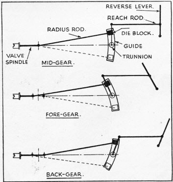
THE PRINCIPLE OF JOY’S GEAR is illustrated in this diagram. Movement of the valve spindle is derived from the sliding of the die-block in a guide pivoted on a pair of trunnions. In mid-gear no movement is imparted to the valve spindle. Fore-gear gives the valve a position that will permit the engine to run forward, back-gear starts the locomotive in the reverse direction.
To reverse the gear, the lever is pulled back, and the guides now incline backwards, so that, when the die-blocks are at the top, they are now farthest away from the cylinders, and the nearest position will be at the bottom. This completely reverses the movement of the valves, and so the engine moves backwards.
Two difficulties arose in the practical application of Joy’s idea, and he solved both problems in a simple manner. The first was the operation of the die-blocks. They could not be worked directly from the connecting rods by a simple link, because that part of the connecting-rod directly under the guides moved in an oval path as the engine travelled, and the die-blocks would therefore have received an uneven movement, sufficient to upset the correct steam distribution. The link (called the jack link) was accordingly turned downwards, the end being attached to another and longer link (called the anchor link), the outer end of this in turn being pivoted to a fixed point on the frames; hence its name. The die-blocks were connected to a point near the top of the jack link, by another link known as the vibrating link, and by this means an even up-and-down movement was obtained.
As we have seen in the description of the Stephenson link motion, the valve must be advanced at the beginning of each stroke, to an amount sufficient to start opening the steam port when the crank is on dead centre. If the radius rod connecting the valve spindle to the die-blocks had been attached to them at the same point as the jack-link connexion - that is, at the centre of the blocks, the latter would have to travel a little way along the guides before the valves began to open the ports; this would have made both admission and exhaust points “late”, with consequent loss of power and speed, and increase in steam consumption.
To obviate this, the vibrating link was extended above the die-block connexion and the radius rod coupled to the extreme end. Because of the angularity of the vibrating link when the crank was on each dead centre, the point of connexion was now ahead of, or behind, the die-blocks at the dead centre points, and this extra movement enabled the valves to open the ports at the right time.
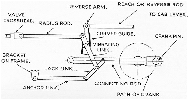
JOY’S VALVE GEAR, invented by the late David Joy in 1879, dispenses with eccentrics, the valve being operated by a dire-block moving in a curved guide. The die-block is connected at its upper end to the valve spindle by a radius rod and by a system of links to the connecting rod. The central pivot of the vibrating link is attached to the die-block.
This valve gear gave excellent results, proved very satisfactory in working and maintenance, and was for many years the standard gear on the London and North Western and Lancashire and Yorkshire Railways for main-line passenger work. As the engines became larger, however, and the gear was called on for more strenuous work, one defect became apparent. The presence of the jack-link pinhole in the connecting rod proved a source of weakness, and several rods broke through the hole while the engines were travelling at speed, with more or less disastrous results. Connecting rods were strengthened up, and the risk of accident eliminated, but with the return to favour of outside-cylinder engines, there came a time when the inside-cylinder valve gear without eccentrics was no longer needed, and no new engines fitted with Joy’s valve gear have been built for many years.
Walschaerts Valve Gear
Walschaerts valve gear is one of the most extensively used gears of modern times; yet it was invented a long time before it came into general use, for the idea was evolved as far back as 1844. The inventor of the gear was a young foreman mechanic named Egide Walschaerts, who was in charge of the locomotive shop of the Belgian State Railways, and was therefore a practical man with experience of other forms of valve gear. He had evidently been having trouble with the valve gears on the engines in his charge; and, not liking the combination of movements which operated the valves, he set to work and devised a gear in which each part did one job, and one only, as we shall see in the explanation of the working.
Walschaerts did not patent the gear himself, as the State Railways would not permit an employee to make personal profit out of an invention; but a friend made the application in his name, and the gear was patented in the year stated above. It was, however, some four years before Walschaerts applied his gear to one of his engines, and the result was most satisfactory.
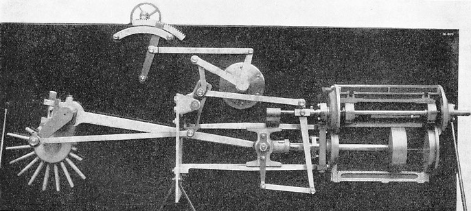
LOCOMOTIVES with piston-valve cylinders can be fitted with Walschaerts gear, as represented by this fine working model in the Science Museum, South Kensington. The gear is set for backward running, and the live-steam space between the piston valve bobbins is seen open to the right-hand or front end of the cylinder. Steam has already been cut off from the back end of the cylinder, and is exhausting.
Improvements followed, the gear attracted the attention of other locomotive engineers, and in due course found a wide application on the continent of Europe. The ever-cautious British locomotive engineers were slow to take up the Walschaerts gear, and for many years the only engine in Great Britain that had it was an 0-4-4 tank which was exhibited at the Paris Exhibition of 1878 and was purchased by the Swindon, Marlborough and Andover Railway in 1882.
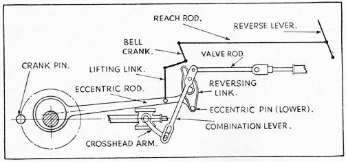
THE ORIGINAL VALVE GEAR designed by the Belgian engineer, Egide Walschaerts, in 1844, employed an eccentric in conjunction with the crosshead to operate the valve. The T end of the eccentric rod carries two pins; the lower pin is shown engaged with its slot in the reversing link. On lifting the eccentric rod, so that the top pin engages with the upper slot in the link, the direction of the engine is reversed. The combination lever is pivoted on the pin of a crank attached to the reversing link shaft.
In 1890, Messrs. Beyer, Peacock & Co built some tank engines for Ireland and fitted them with Walschaerts gear; then came another lull. Meanwhile, the gear was going ahead on the Continent, had spread to America, and was being applied by private British locomotive-building firms to engines constructed for colonial and foreign railways. At long last the Walschaerts gear received its welcome in Great Britain, and by 1913 about 150 locomotives were running with it. At the present time it holds the field in Great Britain, the LMS and Southern Railways fitting it to all new engines. Its only rivals on the LNER in new stock are a few poppet-valve gears which are cam-operated. The Great Western Railway, however, still makes extensive use of the Stephenson link motion on its two-cylinder engines, and uses Walschaerts only for those with four cylinders. In America the Walschaerts gear remained supreme for a time, but it now has a formidable rival in the Baker gear, which will be described in a future chapter, with one or two other systems of lesser importance but equal interest.
Egide Walschaerts’ first design was really the Carmichael gear “turned inside out”, with a lap and lead movement added. The Carmichael gear is described in the chapter beginning on page 834. Similarly to the Carmichael gear, Walschaerts employed a single eccentric set at right angles to the crank; but instead of the gabs being attached to the eccentric rod, they were turned about, combined to form a sort of oval link, and attached to the equivalent of the upper arm of the Carmichael rocking lever, the lower arm being dispensed with altogether.
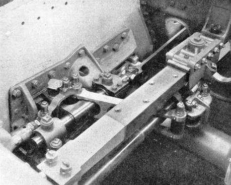
STEPHENSON-MOLYNEUX system for the employment of Walschaerts gear to actuate the valve motion of inside cylinders. Note the special form of combination lever placed horizontally. The intermediate valve spindle worked by the eccentric and carrying the left-hand end of the combination lever is clearly seen alongside the rectangular guide bar in the centre of the picture.
When the eccentric rod was driving the upper end of the link, the arm moved in unison with it; when driving the lower end, the arm moved in the opposite direction, and the engine was thus reversed. To obtain the lap and lead movement, the valve rod was not directly connected to the pin in the rocking arm as in the Carmichael gear, but to the upper end of a rod swinging on this pin. The lower end of the hanging rod, which was slotted, was oscillated by a connecting link from the crosshead. As in the Joy gear, the angularity of this rod, when the engine was on dead centre, advanced the valve far enough to start opening the steam port.
So far, so good; but the oval link allowed for only a limited range of expansive working. Walschaerts, therefore, set to work to improve it, and after some experimenting, evolved the gear as we know it to-day.
The principal improvement consisted in making the eccentric oscillate a link, which was altered to the Gooch curved-slot pattern, with a die-block attached to the valve rod, or radius rod, as it now became. The die-block could be moved from one end of the link to the other, or held in any position in the slot, so that it moved either in unison with, or directly opposite to the eccentric, and its travel could be shortened. The lap and lead movement was made an entirely separate component. A fork, or small crosshead, was attached to the valve spindle, and a vertical rod, called the combination lever, was suspended from this. The radius rod was attached to the combination lever directly below the valve spindle fork, and the lower end of the lever was connected by a short union link to a dropped arm on the main crosshead.
It will now be seen that each part of the gear had one job allotted to it, doing just that one job, and no more. The eccentric actuated the link; the link moved the die-block, which in turn moved the radius rod, keeping the valve in correct relationship to the piston for either forward or backward motion, according to the position of the block above or below the centre of the link. The crosshead arm and union link oscillated the combination lever, which gave the valve spindle the additional movement needed to open the steam and exhaust ports at the correct times, and so the steam distribution was correct.
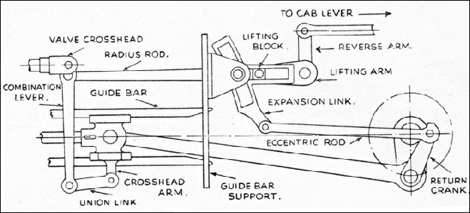
WALSCHAERTS VALVE GEAR, with direct-lift reverse shaft as fitted to locomotives with slide-valves, giving steam admission over their outer edges. Where Walschaerts gear is used for piston valves with steam admission over their inner edges, the radius rod is attached to the combination lever above the valve crosshead and not below it. The radius rod and lifting mechanism and other details may vary in design, but the underlying principles of the gear remain unchanged in all instances.
While the principle of Walschaerts gear remains as above on the locomotives of to-day, the construction and details vary considerably; and, with inside-admission piston-valves, the connexions at the top of the combination lever are reversed. When the gear is placed between the frames, as on the Great Western four-cylinder engines, and on the Southern and LMS three-cylinder engines, which have separate sets for the inside cylinder, the links are oscillated by eccentrics, as in the original design. With outside-cylinder engines, the eccentric is displaced by a return crank, which reduces the friction to a minimum, especially when the eccentric rod is fitted with ball or roller bearings, which is becoming common practice. The expansion link bearings are attached to short girders which are bracketed to the frames, or else directly attached to a small frame bolted to the guide bar bracket or support.
In American and similar types of overseas engines having bar frames it is usual to fix a heavy yoke right across the frames, and make this support both guide bar brackets and expansion links. The links themselves are of various forms; there is the single open link as used on the Southern and other lines, which consists of a plain slotted link, with a small “wing” on either side, to carry the trunnion pins by which the link is hung. Then there is the three-piece link; this has a slotted link mounted between two plain links, with distance-pieces at top and bottom. The single die-block works in the slot, the radius-rod being slotted and embracing the central link, while the plain outside links carry the trunnion pins.
The box link is common in America, and it is used also on the Great Western and LMS Railways. It consists of two curved slabs of metal, resembling the slides in a Joy gear, the adjacent sides of which have grooves cut in them to accommodate the two die-blocks. The radius rod used with this type is straight, and passes between the two sections. Most links have a “tail” carrying an eye for connexion to the eccentric rod, and this tail is set backward a certain amount from the vertical centre-line of the link, to compensate for the angularity of the eccentric rod when it follows the movement of the return crank, and to obtain an equal amount of swing on either side of the centre. Some of the box links on the GWR and LMS have no tail, but are driven by a pin in the lower part of the link itself.
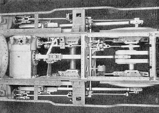
THREE CYLINDERS of a locomotive, built by Robert Stephenson and Co, for the Buenos Ayres and Pacific railway. Steam to the inside cylinders is controlled by the Walschaerts valve gear arranged on the Stephenson-Molyneux System. Note that the slotted link is operated by an eccentric adjacent to the central crank. The combination lever is arranged horizontally as shown.
The radius rods are lifted and lowered by three principal methods; in two of them a weighbar or reverse shaft with lifting links is provided, exactly as described for the Stephenson link motion, the connexion of the lifting links to the radius rod being either in front of or behind the expansion link. The third and most satisfactory method is to run the weighbar or reverse shaft through two bearings in the frame, on the centre line of the link trunnions. The radius rods extend beyond the links, and are slotted; the arms of the weighshaft operate them direct by means of sliding blocks attached to the arms and working in the radius rod slots. The radius rods thus move in a straight line, and the small amount of die slip existing is equal at either end of the link.
To prevent undue wear on the valve spindle bushings, most of the valve spindles are provided with a small crosshead and guides, which take the weight of the combination lever, and prevent it from coming on the spindle. On many American and overseas locomotives, where the distance between piston-rod and valve-spindle centres is considerable, the drop arm usually attached to the main crosshead is dispensed with, and the union link coupled direct to the crosshead pin. Everything possible is done to save weight in modern Walschaerts valve gears, the parts being made of the best grades of heat-treated, high-tensile steel, and as light as possible consistent with strength.
Although the Walschaerts gear is best suited to cylinders having the valves on top, it is not difficult to apply it to cylinders having valves at the side. On the Southern Railway’s “Baltic” tanks, recently converted to 4-6-0 tender locomotives, the cylinders are outside and the steam chests and valve spindles inside. The spindles are operated by a double “pendulum” shaft, the inside arm being connected to the valve spindle, while the outside arm is driven by the valve gear, the combination lever of which is suspended from it.
An Ingenious Inside Drive
The gear is well designed, very neat, compact and efficient. The locomotives themselves had the largest cylinders of any passenger tank engines in Britain, and until the advent of electric traction for main-line trains, worked the fastest and heaviest express services of the late London, Brighton and South Coast Railway over fairly difficult routes, with the greatest of ease and the maximum of reliability.
On an inside-cylinder engine fitted with Walschaerts gear there is often some little difficulty in arranging the necessary clearance for the swinging of the combination levers. On the Southern engines of the U1 class, this has been overcome in an ingenious manner by using a very short combination lever, and driving it by an extra eccentric set “in step” with the crank. This gives the necessary synchronism of movement, but as the stroke of the eccentric is only a few inches compared with the full stroke of the crosshead, the combination lever need only be of proportionate length, and all clearance difficulties are avoided.
Another ingenious inside drive has been applied by Messrs. Robert Stephenson & Co., Ltd., the builders whose experience dates from the “Rocket”, to some three-cylinder engines for the Buenos Ayres and Pacific Railway. Each of these engines has an inside cylinder with the steam chest at the side, and the arrangement of valve gear, known as the Stephenson-Molyneux system, makes it possible to use the ordinary simple form of Walschaerts gear in conjunction with a horizontal combination lever. The radius rod drives an intermediate spindle running in two bearings attached to the frame, and on this is mounted a special crosshead which carries what would be the top bearing of the combination lever it the latter were vertical. A forked link connects the valve spindle itself direct to the combination lever, the tail of which is also bifurcated, the piston-rod passing through the fork, which is connected to the main crosshead by a special form of union link. Thus the horizontal combination lever functions in exactly the same manner as its vertical counterpart.
It is, however, for outside cylinders that Walschaerts valve gear has been most generally adopted. On the railways of the United States, Canada, and other countries where vast distances have to be travelled far from repair shops, the facility with which adjustments and lubrication of the working parts can be effected has helped in popularizing the gear.
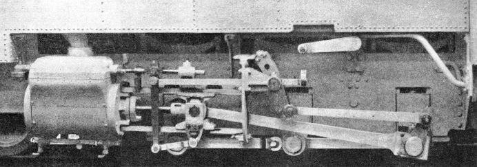
ON A GREAT WESTERN TANK LOCOMOTIVE used on the Vale of Rheidol line. Walschaerts valve gear is fitted. The radius rod is attached to the combination lever below the valve spindle crosshead, as the cylinder’s steam supply is controlled by slide valves with admission over their outside edges. (The above picture shows the application of the gear illustrated in the last diagram above.)
You can read more on “Driving a Locomotive”, “Locomotive Accessories”, “Locomotive Valve Gears- 1” and “Locomotive Valve Gears - 3” on this website.


