
© Railway Wonders of the World 2012-

The Vacuum Automatic Brake
Stopping Trains by Atmospheric Pressure

A MODERN COACH fitted with the vacuum automatic brake. A is the brake cylinder, B the vacuum reservoir and C the brake rod.
THERE is a saying that “competition is healthy”. This in railway mechanics is decidedly so, as it makes for efficiency. One of the most outstanding examples is that of the rival braking systems, compressed air and vacuum.
Both are efficient and reliable; each possesses advantages; and before the general grouping of the railways, each had its adherents. The London, Brighton and South Coast, Great Eastern, North Eastern, London Chatham and Dover, and other lines used the Westinghouse air brakes, while the London and North Western, London and South Western, Great Northern, Midland, and others, pinned their faith to the vacuum automatic brake. Perhaps the best example of the rival brakes working side-
The vacuum brake was invented while the compressed-
Again repeat the first experiment; this time do not uncover the nozzle, but let go the piston-
The ejector is oneself, the rubber tube is the train pipe; the syringe is the brake cylinder; and if one attached the pull-
As with the compressed-
The locomotive was fitted with an “ejector”, consisting of a casing containing a cone with a steam nozzle at the back of it, steam being supplied from a valve on the boiler backhead.
The rear end of the cone was connected to the train pipe via the driver’s valve, which acted the same as a three-
When the driver wanted to apply the brakes, he opened the steam valve, and placed the brake valve handle in the first position. Steam blew through the cone and took the air from the train pipe with it. This mixture went to the smoke-

THE ARRANGEMENT OF THE VACUUM AUTOMATIC BRAKE. The numbered parts of the combined cylinder refer to 1. Cylinder; 2. Piston; 3. Cylinder casing; 4. W.I. Piston rod; 5. Piston rod packing box; 6. Piston rod guide bush; 7. Piston rod cap; 8. Rolling ring; 9. Joint ring; 10. Piston rod gland packing ring; 11. Ball valve; 12. Ball valve cage and spindle; 13. Ball valve diaphragm; 14. Release lever of ball valve; 15. Ball valve insertion joint; 16. Cylinder hose pipe.
When the air was drawn from the train pipe by the ejector, the pressure of the atmosphere would close up the “concertinas” and so exert a pull on the brake rods. With air in the train pipe, pressure was equal inside and outside the “concertinas”, and the brakes would either release themselves or else be pulled off by release springs, as in the case of the air brake.
The vacuum brake, in this primitive form, underwent several improvements; the steam and brake valves were combined, so that the brakes could be applied or released by movement of one handle only. Various details were made better; but the brake as a whole suffered from drawbacks similar to those of the “straight” air brake. If anything happened to the ejector or apparatus on the engine, or if leakage occurred in the train pipe and connexions, the brake could only be applied with reduced power, or not at all. It was sluggish in operation; also -
Automatic Application
Again, as in the case of the air brake, one small gadget added to the brake cylinders reversed the action of the brakes, and made them automatic. This was nothing more formidable than a simple ball valve, located at the point where the connexion from the train pipe was attached to the brake cylinder.
The brakes were now “off” all the time a vacuum was maintained in the train pipe; and as soon as air was admitted, either by the driver, guard, or by accident, the brakes were automatically applied, the action being as follows:
When the engine was coupled on to the train and the driver opened the ejector steam valve, the air was extracted from the train pipe, but this did not apply the brakes, as air was taken from both sides of the pistons in the brake cylinders, leaving them in equilibrium, or “balanced”. And as long as the pressure or vacuum on both sides of the pistons remained equal, the brakes stayed in the “off” position. Air was drawn by the ejector from the undersides of the pistons direct; but to get from the upper side of the pistons, the air had to lift the ball valve and pass through it.
To apply brakes, the driver pulled back the handle of the brake valve, which first cut off steam from the ejector, and then admitted air to the train pipe. This rushed along to the undersides of the pistons, but was unable to get into the space above them, as it forced the ball valves down on their seats and held them there, effectually barring its own passage. Pressure on the undersides of the pistons now being greater than the pressure above them, they were forced upwards; and the rods being coupled to the brake gear through the usual pull-
This is the action of the automatic vacuum brake, as used to-

THE BRAKE FITTED. 1. Stop valve; 2. Super Dreadnought ejector; 3. Duplex gauge; 4. Siphon; 5. Cylinder; 6. Vacuum chamber; 7. Drip Trap and valve; 8. End pipes and couplings; 9. Cylinder; 10. Siphon; 11. Van valve; 12. Gauge; 13. Passenger communication pulls; 14. Air valve.
It will be seen from the above description that to operate the vacuum brake on a train of modern weight and length, an efficient ejector is needed to extract the air with the utmost rapidity from the train pipe when releasing the brakes, and to maintain the vacuum while running, as there is always a certain amount of leakage at hose connexions and other places.
About the best known is the “Dreadnought” type. This ejector is fixed either on the right or left hand side of the cab, according to which side the driver stands. It consists of a gun-

VIEW OF ENGINE CAB SHOWING EJECTOR. A is a Great Western engine-
The “brake off” position is used to release the brakes quickly, after they have been applied to stop at a station, or for a signal stop. And in this position, steam at full pressure passes through the large cone in the ejector body, rapidly extracting the air from the train pipe, and blowing it away through the exhaust pipe and up the engine’s chimney. This explains the origin of the peculiar whistling roar which many locomotives make just as they are on the point of stopping, and which puzzles “non-
When the brake handle is in “running position”, steam is cut off from the large cone, but continues to pass through the smaller one. This maintains a kind of “pull” on the train pipe all the time the train is running; by extracting any air that gets in through leaky hose couplings and so on, keeps the brakes released. The noise made by the steam passing the small cone and blowing up the exhaust pipe has frequently been ascribed by “non-
Although the principle of the ejector has remained the same from the beginning, there are various forms of ejectors in use, and they have been greatly improved in detail, principally in the reduction of the amount of steam needed for the extraction of a given quantity of air. One of the latest is the “super-

A CLOSE-
Some railways, notably the Great Western and the LNW section of the LMS, use a pump to maintain the vacuum while the train is in motion. They can thus dispense with the continuous blowing of the small ejector cone; the ejectors on the engines have the large cone only. Engines fitted with vacuum pumps give audible notice of it by the loud “ticking” sound they make when running, caused by the action of the pump valves. On outside cylinder engines the pump is usually attached to the guide-
As these pumps are fairly powerful, and would create in the train pipe a vacuum higher than that created by the ejector, a relief valve is usually fitted so that the vacuum in the train pipe shall not exceed a certain figure. This is like a safety valve working “upside down”, the pressure of the atmosphere opening the valve and allowing the air to enter when the pump is doing its duty in too conscientious a manner.
If a high vacuum is created in the train pipe, naturally it will be the same in the brake cylinders also; and unless the ejector can create a vacuum equal to that in the brake cylinders above the pistons, the brakes will not release after application and it means “pulling the strings” right through the train and starting all over again.
The full working range is between 18 and 25 in of vacuum, the brakes usually being worked between 21 and 23 in. Vacuum gauges are provided in the engine cab and the guard’s van, and are calibrated in inches instead of pounds for very much the same reason that one says there are “two degrees of frost” when the thermometer stands at 30 degrees Fahrenheit, or two degrees below freezing point. If one had a glass tube bent U shape, and put some mercury into it, the mercury would rise to the same height in both legs of the tube; and there would be equal air pressure (about 15 lb to the sq in at sea-
As there is only this comparatively low pressure available to work the brakes, the brake cylinders have to be much larger than those used in compressed-
The whole is made of thin cast or pressed metal, the working cylinder being covered by a dome-
Brake Cylinders
The piston is hollow and very deep, and contains a long packing groove in which is a big rubber ring, of circular section; a glorified edition of those used to seal preserved fruit jar caps. As the piston moves, this ring rolls between piston and cylinder, and forms a perfectly airtight yet practically frictionless packing. The piston-
Other types of brake cylinders are in use. One kind does not use a rolling ring nor a ball valve; the ring is replaced by a rubber band operating in much the same way as a cup leather on a cycle-
Another kind of “sack” is used in a horizontal position under the carriages, similar to air brake cylinders, and contains two diaphragm pistons. The space between them is always under vacuum; to apply the brakes, air is admitted at both ends. Sometimes the piston-

A FAST GOODS WAGON fitted with vacuum brakes. The vacuum reservoir and brake cylinder can be seen beneath the wagon flooring. The belt-
Some brake cylinders are fixed, the piston-
The guard can apply the vacuum brake from his van, the valve being of the lift type in a casing, and operated by a handle which unseats it to admit air to the train pipe. This valve also has an automatic action which assists the driver to make a quick stop in emergency. The casing above the valve is under vacuum, as it communicates with the train pipe through a small hole in the valve stem; consequently a rush of air into the train pipe acts against the underside of the valve, as it acts on the piston of the brake cylinder, lifting it against the vacuum in the casing. Air then rushes in and helps to apply the brakes quickly. On some lines where slip coaches are used, a special arrangement is provided whereby the guard can apply and release the brake as well, so that he can stop the slip portion of the train at the required part of the platform.
Passengers also can stop a train if necessary. The passenger alarm signal is directly connected to the brake gear, so that anyone wishing to stop the train in emergency begins to apply the brakes. A small pipe connects the train pipe with a valve box on its end of the coach near the top, the valve consisting of an India-
 The train is finally brought to a standstill by the driver or guard.
TWO BRAKES IN ONE. This apparatus is fitted in the cab of a locomotive and controls the vacuum brake for the train and also the steam brake for the engine itself. The long lever shown to the left of the picture is for operating the steam brake when the engine is running without a train. The vacuum brake and ejector handle is seen at the extreme right and the ejector regulator at the top centre.
Every brake system must necessarily present difficulties, and many ingenious devices have been invented and perfected by railway engineers to ensure reliability of the vacuum brake under all conditions.
An important, though small, component of vacuum brake equipment is the “drip-
On the vacuum being restored, the ball is again drawn upwards against the seating, scaling the trap against the pressure of the atmosphere.
Hose couplings, which join the brake pipe of one coach to that of the next throughout the train, are always a source of interest to the travelling public. Half the fascination of watching a railwayman “couple-
Uncoupling is easily accomplished by lifting the two fittings apart. The last hose-
In some instances couplings are used with extra long lugs, provided with a chain and pin. Where vehicles of differing types, for example, are to be coupled together, the position of the flanged castings would not be at the bottom of the “U” formed by the hoses, but the pin through the lugs holds the flanges in close contact, despite the fact that they are hanging nearly vertically.

INSIDE THE BRAKE CYLINDER. The pressure of the air (indicated by dots) in the train pipe moves the piston in the brake cylinder. The cylinder is surrounded by a dome-
nother very interesting type of coupling is that used between an engine and tender. This coupling is placed on the auxiliary pipe between the engine and tender, and retains the automatic action of the brake in the event of the locomotive being accidentally separated from the tender when running. Each half coupling is fitted with a ball which, when the coupling is together, is held off its seating by means of a protruding peg on the other half. Should the engine break away from the tender, these balls are forced on to their seatings by the inrush of air, and the pipes thus become sealed.
The application of the vacuum brake to a locomotive has been illustrated early on this page, but under modern conditions it has not always been practicable to make use of this system. In certain instances there is not sufficient room on a locomotive for a brake cylinder large enough to be effective, and consequently a brake is employed which is operated by steam at the full pressure of the boiler. It is generally the custom to make use of the vacuum brake for the train and the steam brake for the locomotive. The two systems are used conjointly, and their action is simultaneous. This is effected automatically by means of the control gear of the vacuum brake, which also governs the action of the steam brake on the locomotive. The ejector in the locomotive cab, which controls the vacuum brake on the train, is fitted with a special valve automatically controlling the operation of the locomotive steam brake.
In this apparatus, shown by the illustration above, a piston is held in place by the vacuum in the train pipe, and this in turn maintains a steam valve on its seating against the pressure of steam in the boiler. When the brake is “off”, the effect of the vacuum on this piston resists pressure of the steam. But when an application of the brake is made the power of the piston is reduced, and steam rushes through the valve, previously closed by the piston, and enters the steam brake cylinder, so applying the engine brakes to the wheels. When the vacuum is restored in the train pipe the steam is allowed to escape from the brake cylinder, which at the same time is shut off from the main steam supply of the boiler.
The partial application of the vacuum brake also ensures a partial application of the steam brake, so that the locomotive shall be retarded in equal proportion to the train.
The vacuum automatic brake is also used on electric trains on certain railways, the vacuum being created by an exhauster, driven by an electric motor.
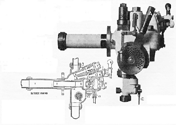
A SUPER-
THE INTERIOR OF THE EJECTOR. 1. Exhaust barrel;
2. Large cone, inner part; 3. Small cone; 4. Additional small cone; 5. Large cone, outer part; 6. Valve gear for large ejector steam supply; 7. Cover for additional small cone; 8. Regulator handle for small ejector steam supply; 9. Cover for small cone; 10. Gland and cam for small ejector; 11. Lever for air lock; 12. Large cone cover; 13. Spring for air lock; 14. Body of ejector; 15. Air disk shaft; 16. Drip valve for air lock; 17. Main drip valve.
You can read more on “Automatic Safety”, “The Magic of Modern Signals” and
“Stopping the Train” on this website.