
© Railway Wonders of the World 2012-


A Scottish District Subway
Glasgow’s Unique Underground Railway
GLASGOW has the distinction of possessing the only underground railway in the world that was originally planned for operation by cable traction, and the only one that has used this method of working continuously from its opening until its recent electrification. This unique railway all the more merits description, since the cable railway has now joined the atmospheric railway as a thing of the past.
The Glasgow District Subway is a circle railway, about six and a half miles in length, constructed at an average depth of 29 ft beneath the surface. The line passes under the River Clyde on both its eastern and western sections, and it has no fewer than fifteen stations. The depth of the line varies considerably, ranging -
The promoters of the railway decided from the outset that the steam locomotive was unsuitable for underground working; but for some time, as happened to so many of the earlier railways in this country, they could come to no conclusion regarding the type of motive power most fit to be employed. Their Act of Parliament merely empowered them to make use of “any system of haulage other than by steam locomotives”. The claims of electricity were strongly, but vainly, urged on the directors, who took an unnecessarily cautious view. Apart from the Brighton Electric Railway and the Giant’s Causeway and Portrush line -
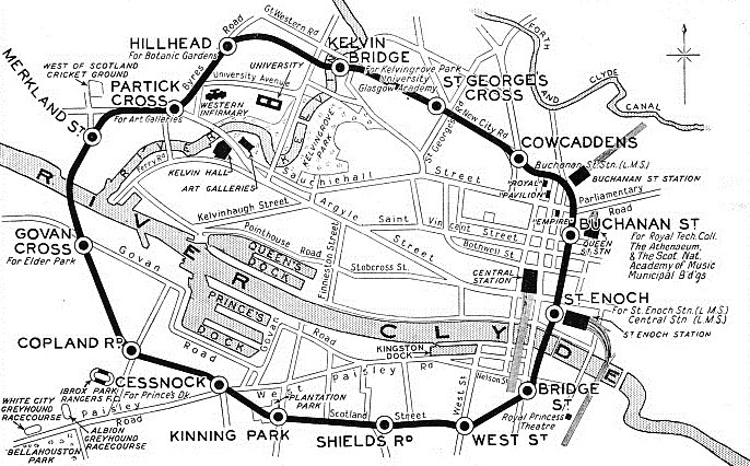
BELOW THE STREETS OF GLASGOW. This map shows the six and a half miles route of the subway, which has recently been converted from cable to electric traction.
The subway was opened for traffic on December 14, 1896; but, owing to an accident, the service was obliged to close down the same day, and the line did not open for regular working until January 19, 1897. Since 1923 it has been owned and operated by the Corporation of Glasgow, in conjunction with tramway system. The gauge is the unusual one of 4 ft.
The subway is carried in twin tunnels, nominally 11 ft in diameter, which lie side by side at distances varying from 2 ft 6 in to 6 ft. The inner and outer lines are thus kept distinct, save at the stations, where the tunnels merge into a single arched tunnel with a span of 28 ft. Except in those sections where it was necessary to line the tunnels with iron (under the Clyde and elsewhere where geological conditions necessitated reinforcement), connecting passages, or manholes, are placed at intervals of 25 yards. Curves and gradients are, in the main, on the easy side, but the western and eastern under-

A CONVERTED COACH. When the subway was electrified, the rolling-
The cable system was characterised by a number of unusual features. There were two cables, driven by steam from a main power station, one for each tunnel. Each cable was an inch and a half thick, and weighed about 57 tons. The cables were placed between the tracks, kept in motion during the whole of the time that the line was open to traffic, and ran at a uniform speed of twelve and a half miles an hour. Beneath the cars was a gripper device. When this was applied to the cable the cars moved forward, while its release brought them to a standstill. The gripper itself was composed of two steel jaws, of which the bottom one was fixed, while the upper one was designed so as to be raised or lowered on the actuation by the driver of an arrangement of links and levers. It will be seen that this method provided a simple means of starting and stopping the trains on a line on which the haulage cables were in continual motion.
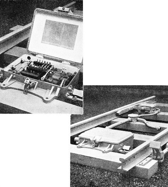
A SAFETY DEVICE incorporated in the Glasgow District Subway is the train-
Where the cable system has been used on tramways it has always been necessary to place the cable in a conduit, both because of the risk of damage, and because of the danger and inconvenience to other traffic if it were not carried below track level. On the Glasgow Subway the cable was raised, so that the lowest part of the gripper could project several inches above the rails. Normally the gripper gear was worked by a hand lever; but, to guard against the contingency of this not being used by the driver at the crossovers where the cables entered and left the power station, a small roller was provided for the purpose of making with bar between the rails. This contact automatically brought the operation. To stop a train at a station the upper jaw of the gripper was raised so as to bring it slightly out of contact with the cable.
The railway has always been handicapped by certain features of design and equipment that place special difficulties in the way of operation, and cannot be done away with save at prohibitive cost. Among those handicaps is the small size of the stations, which is responsible for the limitation of the trains to two cars; the gauge, which has complicated the work of electrification; the difficult station approaches; and the entire absence of crossovers or sidings. This last stereotypes the train service, since there are no facilities for “laying by” cars during periods of minimum traffic requirements.
Another difficulty is that there is no accommodation for the proper stabling of the trains when they come off duty at night. It is necessary to “bunch” them in the tunnels for cleaning and repairs; and, should a car have to be brought to the surface for heavy repairs or overhaul, it has to be lifted to the workshops at street level by a crane, an operation that can be carried out only during non-
Reference has already been made to the “nominal” tunnel diameter; this is, in fact, not uniform throughout, and in places the walls have encroached to such an extent that it was found impossible to mount the “live” conductor at the usual height at the side of the running rails. Thus, to secure an adequate clearance between the tunnel walls and the carriage bogies, a higher elevation was adopted, in which position the brackets supporting the live rails had to be designed specially so as to obtain the necessary degree of rigidity. The solution here was to mount the brackets on steel sleepers, with intervening sleepers of hardwood; but this in turn produced another problem, since the use of steel sleepers prevented the employment of track circuiting.
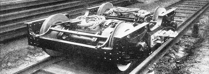
THE TRACTION GEAR on one of the bogies of the reconstructed coaches. To allow for the mounting of two 60 hp traction motors on each bogie the wheel base has had to be increased to 5 ft 6 in.
The problem has been solved by utilising the conductor rails from which current for lighting is supplied to the trains. These conductors, which are fed by alternating current, and are carried on the walls of the tunnels. have been divided into signalling sections of suitable length, the lighting current thus operating the signals. In normal conditions, only one train occupies a section at a time; when this is occupied the lighting current actuates the signal, and, since the current does not flow when the section is unoccupied, the “line clear” indication is given. To guard against the remote contingency of a train entering a section with extinguished lights, a “track instrument” is installed at the entrance to each signalling section, and the passing of a train over this appliance automatically puts the signal protecting that section at danger until the section is cleared. The equipment includes also the automatic train stop and the trip cock as used on the London Underground railways. In addition, there are tunnel wires throughout the system. These not only enable the traction current to be cut off in an emergency, but can be used also for telephoning to the nearest station in the event of breakdown in the tunnels, the drivers being provided with telephones.
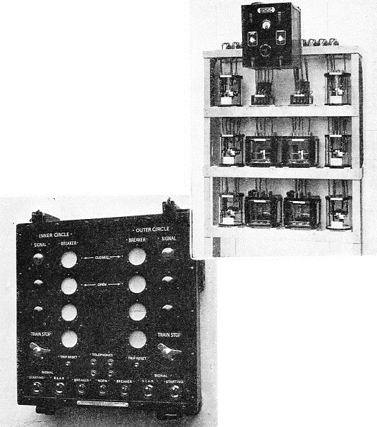
THE CONDUCTOR RAILS from which the train lighting current is taken are also used for signalling purposes. The lighting conductors are divided into sections. When a section is occupied the current for lighting the train is utilized also to give the proper signal. If a section is unoccupied no current flows and the signal shows a clear aspect. The illustrations show (bottom) the signal indicator, and (at the top) the signal relays.
Another feature of the equipment is that every station master is given control over the power supply within the section of line under his jurisdiction. At each station there is a building for housing the traction switch gear, the telephone equipment, and the relays and other signalling apparatus. An indicator panel shows the station master the position of the signals on both the inner and outer running roads. Three-
Reconstructed Rolling-
The electric rolling-
As originally constructed, the seating of the coaches was arranged longitudinally, as on the early City and South London Railway stock. Although in more recent underground railway vehicles the combination of cross and longitudinal seating has been employed, it has been decided to make no alteration in the seating of these converted Glasgow Subway coaches. The reasons adduced are that not only is the design considered to facilitate the entrance and exit of passengers, but that it also makes easier the inspection and repair of such appliances as the pneumatic door control gear and collapsible gates.
The coaches have no middle doors, but there is a wide entrance and exit platform at either end, similar to those provided on the original Central London Railway vehicles. In the cars of the Glasgow Subway, since this design involves the use of the front vestibule both by the driver and the passengers, special precautions have been taken to prevent the manipulation of the control gear by any unauthorised person.
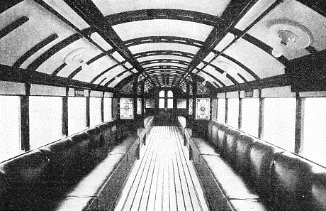
SEATING FORTY-
The track work of the subway consists of 80 lb rails for the running roads, and flat-
Reference has been made to the fact that the station dimensions preclude the employment of more than two cars to a train; but electrification has, of course, greatly increased the capacity of the system. With cable traction the average speed was considerably less than that of a modern tramway, since the twelve and a half miles an hour at which the cable was operated was materially lower than the overall speed, after allowing for starts and stops.
An interesting and unique chapter in railway history ends with the transformation of the Glasgow District Subway from cable to electric traction. While many steam railways have changed over to electrical operation, and many more will doubtless do so in the future, there is no other instance of an important urban passenger system giving up cable haulage for electric traction after nearly forty years of working.
You can read more on “Railways of Caledonia”, “Railways Under London” and
“The Underground Electric” on this website.