Experimental Services Designed to Speed-up Travel
LOCOMOTIVES - 20
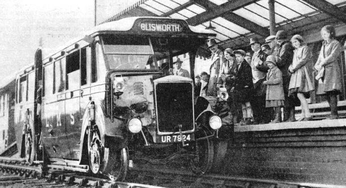
ROAD-RAIL COACH at Stratford-on-Avon Station. A motor coach for road or rail was brought into service by the LMS as an experiment in 1932. The change-over from road to rail took less than five minutes.
IF a broad view is taken of the transport conditions of most civilized countries having the usual road and railway facilities, it must be agreed that the road motor vehicle, whether it is used for passenger carrying or for goods conveyance, has some definite advantages over the rail vehicle. It is not limited to a single track between two fixed stations. The motor vehicle can carry its loads over a network of roads from door to door, without the necessity of transhipment. Further, its use is generally independent of any other ordinary road traffic, and it can start at any convenient time without affecting other road services.
The railway goods or passenger vehicle, on the other hand, must keep to its own track and also to a timetable arranged to keep the track clear at certain specified times only. Moreover, the railway station or goods depot is often a considerable distance from the destination of the passenger or goods, and some supplementary form of transport becomes necessary. With goods traffic, the usual procedure is to load the goods intended for transit on to a motor lorry, convey these to the railway depot, and unload them on to the railway trucks or vans. After reaching the nearest station or depot on the railway line the goods must be unloaded from the railroad on to another motor vehicle, conveyed along the roads to their destination and then unloaded once more This method of goods conveyance not only involves an appreciable loss of time in transit, but also necessitates two loadings and unloadings, with the added risk of damage during these processes; moreover, it necessarily adds to the cost of transport.
In view of these disadvantages it might be thought that to use the railway at all is a doubtful policy where small quantities of freight of, say, two to four tons are concerned, when the goods could be conveyed from door to door without employing the railway. The answer to this is that in partly developed districts, and in areas where the roads are either bad or are congested, it is very much quicker to send goods by rail. The speeds employed on railways are normally much higher than those on the roads. For long distance work, also, the advantages of rail transit are indisputable; moreover, the transit costs are lower.
In many undeveloped or partly developed countries there is generally a railway joining the main towns or industrial areas, and a network of roads leading to the railway stations and depots but there are few long distance main roads. And it is here that the railway scores over the road vehicle; for the latter cannot be used without suitable roads.
From these considerations it seems that in its own sphere of operation the motor road vehicle and the railway vehicle each possesses definite advantages.
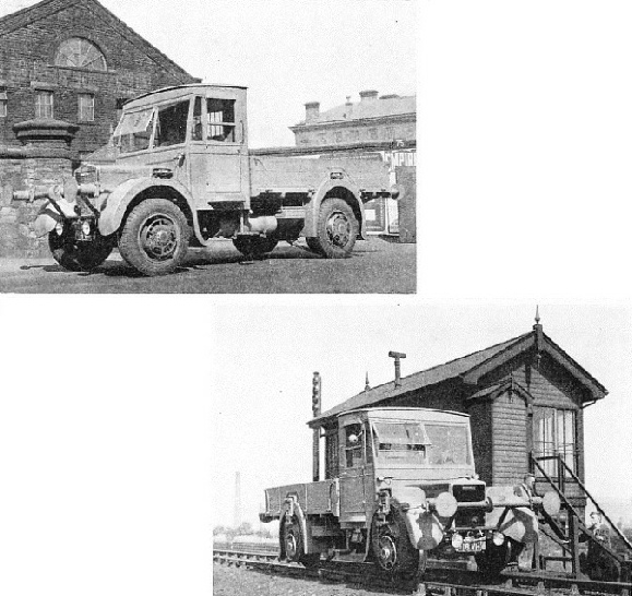
A ROAD-RAIL LORRY built by Karrier Motors for service on the LNER lines. The buffers provided at both the front and rear have special supports fixed to the main chassis.
ON THE RAILS. Another view of a LNER road-rail lorry. The usual power unit for this type of vehicle is a 31-48 hp four-cylinder engine. The maximum road speed is about thirty miles an hour, the rail speeds being somewhat higher.
With a knowledge of these facts it is not surprising that transport engineers have considered the possibility of designing a new type of vehicle that will combine the advantages of each type while avoiding its drawbacks.
After a careful study of this problem, combined with a good deal of research work, a suitable vehicle, known as a “road-railer”, has been evolved. This can run equally well on either the road or the railway track. It can thus begin its journey by road from the loading place to the nearest railway station, and then transfer to the railway lines, becoming for the being a rail-coach. At the end of its railway journey it is once again transferred from the railway track to the road and thence driven off, just as any other motor vehicle, to its destination. It may be of interest to point out some of the more important uses of this combination vehicle.
Its particular application is on branch lines and, especially, on those branch lines where towns and villages lie some distance from the railway. Passengers or goods may be taken on at any convenient place, wherever there is a suitable road. New or partly developed districts lying some distance from the railway can thus benefit materially from the use of the road-railer. Further, the possibility of using this vehicle for week-end and other abnormal traffic must not be overlooked. Road congestion, leading to both slow and dangerous travel, has often created a problem which this new type of vehicle at once solves. Both types of vehicle - passenger and goods - can be attached to trains, with the added advantage that they can be detached when required to proceed to their destinations as ordinary road vehicles.
Apart from its advantages to the railway authorities, the road-railer may be used in various Government services. Its utility in countries where, during certain periods of the year, the rains are so heavy that the roads become impassable, will undoubtedly be recognized, for it will then be possible for journeys to be made over the permanent way.
On the other hand, should a portion of the track be destroyed, or under repair, it is then possible to divert the road-railer on to the road and return it later to the track at the other side of the part which is out of commission. It may even be an advantage to use the vehicle over long distances by rail, and then to cut across country and afterwards connect up with another railway, without having to unload and transfer the goods, as must be done with conventional vehicles.
Perhaps the greatest advantage of the road-railer for use in developed countries, such as Great Britain, is the rapidity and economy with which passengers and goods can be transported over medium and longer distances, from sources and to destinations remote from the railway station.
From the point of view of the passenger service, the low tractive effort necessary to propel the vehicle on the rail results in much lower running costs, due to the reduced fuel consumption and absence of pneumatic tyre wear; this should involve lower passenger fares. Again, when on the railway track the road-railer is capable of travelling, with safety, at higher speeds than it can attain on the roads; thus, with the Karrier road-railer speeds up to sixty miles an hour are well within the engine’s capacity. Further, it is much safer and easier to drive a road-railer on the railway lines than on the roads, for there are practically no obstructions on railway lines.
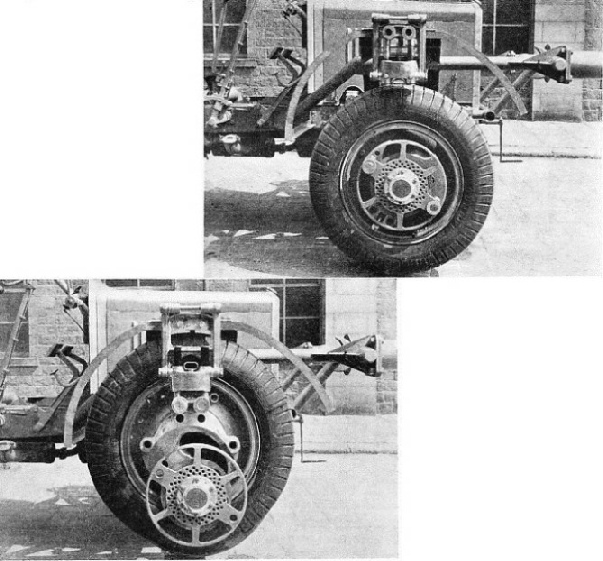
A NEAR VIEW of the Karrier type freight road-railer showing the pneumatic tyre unit in the “road” position. The range of the freighter is from 30 cwt to 8 tons in Great Britain, while abroad it is from 30 cwt to 20 tons.
THE RAIL WHEEL of a Karrier road-railer is placed behind the road wheel, the latter being raised clear of the track for rail working. The road wheel is shown here in the “lifted” position.
From the point of view of the passenger’s comfort, the road-railer has the advantage, well-known to users of motor-coaches, of combining first-class seating with third-class fares. Again, where the railway is the shorter distance between two towns, a certain amount of time is saved. As a goods vehicle the road-railer not only avoids duplicate loading and unloading, but also, owing to the lower fuel costs on the railway track, and to the absence of tyre wear, proves to be more economical than other types of road vehicles.
The various advantages outlined above are embodied in the Karrier road-railer about to be described. This vehicle represents the results of over two years’ experimental work. The first production model was delivered to the London, Midland and Scottish Railway. It was in the form of a twenty-six seat passenger coach, and complied with the Ministry of Transport’s Regulations, as well as those of the railway authorities. Large capacity double-deck passenger vehicles can also be built. The range of road-railer freighters is from 30 cwt to 8 tons, if complying with the Ministry of Transport’s Regulations, but for service abroad they are available from 30 cwt to 20 tons.
The vehicle which ran experimentally on the LMS is fitted with a six-cylinder petrol engine of the usual commercial motor-vehicle design, rated at 37.2 hp, It has a wheel-base of 17 ft 1 in, and road wheel track of 6 ft 3½ in. The rail track is the standard 4 ft. 8½ in gauge. The transmission has a top-gear ratio of 7 to 1 for road use, and 4.2 to 1 for the railway track. These ratios give maximum speeds on the road and rail of 60 and 75 mph respectively. The petrol consumption on the road is 8 miles per gallon; on the railway track it is 16 miles per gallon. The total weight of the vehicle, unloaded, is 7 tons 2 cwts; 3 tons are allowed for the weight of the passengers, staff, and luggage.
The following is the method employed in this ingenious car for converting the wheels from the pneumatic road type to the steel-flanged railway pattern.
Flanged rail wheels are fitted to the vehicle’s axles; on the outside of these are placed pneumatic-tyred road wheels, each of which is mounted on eccentrics fitted to an axle extension through the rail wheel. When on the road, the road wheels are locked concentrically to the rail wheels, which, being of smaller diameter, are quite clear of the road.
The wheel changing operation is as follows. For road to rail transference, the “road-railer” is driven on to the rails at any place where the road has been made up level to the rail tops. Then, with the rail wheels directly over the lines, it is driven forward a few yards until it reaches a point where the made-up road is tapered off. The rail wheels now gradually come into contact with the rails, and take the weight of the machine off its road wheels. The road wheels, which are mounted on an eccentric device, are then raised above rail level by the action of the driver, who rotates them on their eccentrics and locks them to the chassis frame by means of a pin. The road wheels, therefore, do not rotate when the vehicle is moving on the rails. The “change-over” operation is, of course, reversed when returning to the road.
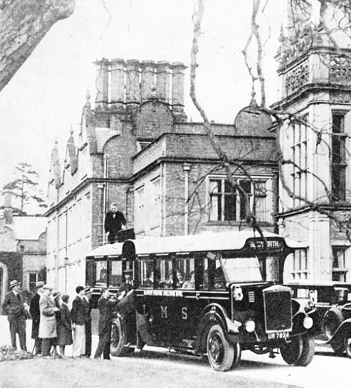
THE ROAD-RAILER motor-coach belonging to the LMS, seen at Stratford-on-Avon. In 1932 the railway company introduced a road-railer which picked up passengers at the hotel, journeyed to the station, and travelled from there by rail to Blisworth, Northamptonshire.
The same principle holds good for both the front and rear wheels of the vehicle. The components are generally interchangeable on all four wheels. Two eccentrics per wheel are employed in this particular design, which enables as much lift to be obtained as is allowable by the wheel rim diameter. The operation of lifting a wheel of the necessary dimensions requires little manual effort. Further, when the road wheel is in a lifted position there is only one bearing in the mechanism which possesses any velocity relative to the main hub. In other words, all the road wheel mechanism remains stationary while the road wheel is out of action. The rear wheels are driven by a propeller shaft in the same way as an orthodox road vehicle, and the drive is cut off from the road wheels by disconnecting two pins which are utilized to secure the road wheels in an eccentric position to the slipper block structure. This structure - one for each wheel - is a device which provides support for the road wheels in their raised position while permitting vertical relative movement between the axle and the frame when the vehicle is on the rail. The structure is hinged in two places, and folds into the body when the vehicle is used on the road. It also offers, due to its radius from the centre of the axle, the required resistance to overcome the static friction between the wheel hub and the inner eccentric bearing. There is no load either on this slipper block structure or on the pins, except that immediately required to overcome static friction between the inner bearing of the inner eccentric and the driving hub when beginning to move on the rail. The pins, however, are of ample dimensions, for they are the medium through which the road wheel drive is taken when the vehicle is running on the road.
It is impossible to insert these pins in the wrong position when raising the road wheels, as the horn block slipper covers up the driving pin hole which is not required and exposes the one into which the pin is to be inserted. The construction of the horn block slipper is unique. It has in its body an automatic lock which prevents the pins from becoming loose when any small vibration is experienced. While this object is satisfactorily achieved, the construction is such that with a minimum of effort, applied sharply, these pins may easily be withdrawn. A similar device is incorporated on the driving hub flange when the pins are inserted for road work. Very long pins ensure that the drive is distributed over wide centres, and their diameter is such as to render wear on the pin bearings highly improbable, on account of the small intensity of pressure to which they will be subjected. When the road wheels are driving, the rail wheels also are revolving, the connexion being made through the outer portion of the hub end which is keyed on a taper to form a connexion between the hub and the driving wheel. The wheel bearings are of the adjustable taper roller type. Another interesting feature is the adoption of the Lang-pattern laminated wood wheel, which possesses both resilience and exceptional strength, and assists greatly in the elimination of track noise. Detachable and renewable steel tyres are employed on these wheels.
As the vehicle runs up to the rail it is impossible to guarantee the position that the driving pins of the road wheel will occupy in relation to the holes in the slipper block. Provision is therefore made whereby the inner eccentric may be positioned in relation to the slipper block. Having established this position it then becomes necessary to ensure the correct relationship between the inner and outer eccentrics. For this reason two slots are provided in the inner eccentric into which the single plunger may operate. After the position of the inner eccentric is located the wheel may be swung round the periphery of that portion of the mechanism. And, when the outer eccentric has assumed its correct radial position in relation to the inner eccentric, the plunger, which has previously been withdrawn automatically from its original slot, now becomes engaged with a slot. This slot has been correctly positioned by its relation with the lower slipper-block pin. This ensures that the two pin holes are in line one with the other, and also in a correct relationship with the holes in the slipper block. It will be seen, therefore, that it is impossible to swing the outer eccentric past its correct centre. The condition is now one in which the inner eccentric is prevented from rotating by the lower pin, while rotational movement of the outer eccentric is also prevented by the upper pin and the spring plunger. It should be made perfectly clear, however, that the two pins substituted in the slipper block are in a position which definitely has disconnected all the drive from the hub to the road wheel of the vehicle in question.
The chassis of the road-railer generally follows conventional commercial vehicle practice. The gear-box, however, is provided with an additional over-speed arrangement to permit of a higher top gear (4.2 to 1), when travelling on the railway, than that used on the road (7 to 1). The braking system serves equally well for both road and rail operation; on the railway, of course no skidding is possible when the brakes are applied. The vehicle may be stopped in a very short distance from speeds of forty to fifty miles an hour without the danger of wheel-lock.
Automatic Lubrication
The tractive effort is ample, and permits the towing of other vehicles. The rear rail wheels are provided with sanding gear. Buffers are provided at both front and rear, special supports for these being anchored to the main chassis frame. There is also a spare wheel carrier fitted at the rear of the chassis. This is mounted on rollers, and it slides automatically to the ground upon release of the attachment fittings. Automatic lubrication is arranged for all the working members of the chassis.
A similar, but improved, road-railer, intended for goods-carrying purposes, is now on duty on the London and North Eastern Railway. It is a two to three-ton freighter employed for duty on sections of the West Highland line of Scotland, between Crianlarich and Mallaig. The vehicle is used mainly for the conveyance of men and materials in connexion with the maintenance of permanent way, and so forth. It travels by road between Crianlarich and Bridge of Orchy, and again between Tulloch and Fort William, where the road gives very convenient access to these stretches of line. Between Bridge of Orchy and Tulloch, however, where the road is not adjacent, and between Fort William and Mallaig, where existing roads are unsuitable, the vehicle travels on the rails, depositing and picking up men and materials as required. This method enables the railway company to effect considerable economies.
The road-railer on this service is fitted with a cab and lorry type of body equipped with fixed sides, and a hinged and detachable tail-board, the inside-body dimensions being 11 ft 2 in by 6 ft 7 in. A sanding device is fitted to assist adhesion. This also obviates wheel-lock and consequent skating, and it enables full use to be made of the servo-assisted brakes.
An improved device for bringing the road and rail wheels into operation is the Karrier “C” slot-type mechanism, which is fitted to each of the four sets of wheels. This is a considerable improvement on the original eccentric device incorporated in the earlier models. It consists of an inner hub carrying a road wheel and a cranked sleeve upon which is mounted the “C” slotted outer hub that carries the pneumatic-tyred road wheel.
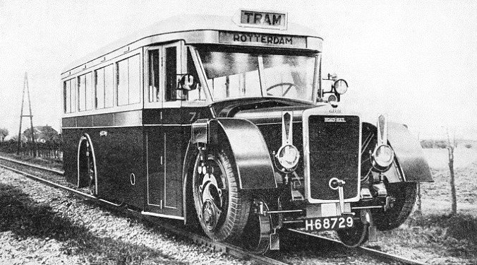
A COACH TYPE of road-railer built by the Karrier Motors, Ltd, for service on the lines of the Rotterdam Tramways in Holland. The wheel-changing operation is easily carried out by the driver.
When travelling over the road, the two wheels are concentric and revolve as one, the drive being taken by two pins which pass through both outer and inner hubs.
When required for service on the rails the road wheel is lifted by means of the eccentric, pivoting about a fulcrum pin carried in a crank, the wheel being supported upon the rail wheel hub by means of a bush working in an oil bath. In its lifted position the road wheel is secured in a non-revolving position by the insertion of the two driving pins - which pass through a hanging bracket carrying a slipper block rigidly attached to the chassis - into two bosses in the eccentric.
The driving flange mounted on the outer hub performs the double duty of transmitting the drive and locking the fulcrum pin during the lifting of the road wheel. It bears a circle of holes so arranged that a special tool may be inserted to engage the fulcrum pin. A cam trigger in the eccentric at a point opposite to the fulcrum pin engages a slot in the driving flange and serves to prevent the collapse of the wheel when driving pins are withdrawn.
The operation of lifting each road wheel is as follows. The vehicle having been run by means of a built-up ramp on to the rails with the road wheels clear of the ground, the two driving pins are withdrawn and the wheel revolved until the cam trigger is at the bottom. It is essential that the fulcrum point be immediately above the axle centre in order to secure the maximum lift, which is 9-in. A special lilting tool is then inserted through a convenient hole in the driving flange into the fulcrum pin behind. The trigger is then depressed, the wheel swung up into the lifted position and secured by inserting the two driving pins through the slipper block into the eccentric. This operation is carried out in respect of each of the four wheels, the total time taken for the “change-over” being well under five minutes.
The Power Unit
The power unit is a 31-48 hp four-cylinder, with a cone clutch and four-speed gear-box. Drive is taken to the rear axle through a propeller shaft equipped with mechanical type universal joints at either end, while the worm wheel and differential gear in the rear axle form one easily detachable unit. Power is transmitted to the wheels - rail (32-in diameter) and road (38-in by 7-in single pneumatic tyres) - by special high tensile steel axle shafts which are of the full floating type, and carry no loads other than torque.
The chassis is fitted with 12-volt electric lighting equipment and is grease-gun lubricated. The maximum legal road speed is 30 mph; the rail speed is 37 mph. There is only one top gear ratio, namely, 6.5 to 1, since the high railway speeds are not so important in a vehicle of this character as, for instance, in a large passenger-carrying road-railer coach. But this lorry type of road-railer has to be of very strong construction to meet the demands of the service.
There is a financial advantage in using the road-railer. Even where Diesel operated rail-cars are in use, unless such vehicles are capable of running on the roads, transhipment of goods to the road vehicle is unavoidable at the end of the journey. Such transhipment requires not only time but also a special staff at the terminus, again adding to the cost. Further, transhipment - as we have pointed out in the earlier part of this chapter - has to be made to road lorries, and the capital cost of these vehicles must be added to that of the rail-car and of transhipment.
It will be appreciated, then, that the road-railer, which not only cuts out all cost of transhipping, also embodies in itself two separate vehicles for little more than the cost of one. This again should have a favourable effect on the use of these vehicles for carrying such goods as farming produce over country roads to the nearest branch line for transfer to the larger collecting stations on the main lines. Since the question of transport costs is of such importance to the farming community in the Dominions and abroad, it seems that here is a solution to one of the principal problems involved.
It also seems possible that the “road-railer” system may be further developed by the provision of convertible trailers, the use of which for road-services has now been adopted by some of the largest transport companies. The hauling of the trailer on the rails would, of course, make but little additional call on the power of the engine.
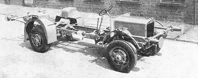
THE CHASSIS of a road-railer used by the LNER. This company uses the road-railer for duty on the West Highland line of Scotland. Men and material are conveyed by the vehicle up and down the line in connexion with track maintenance.
You can read more on “Britain's Diesel Rail Coaches”, “Rail-cars on Rubber Tyres” and
“Railways and Buses” on this website.


